bq25505
SLUSBJ3B –AUGUST 2013–REVISED JANUARY 2014
www.ti.com
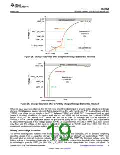
connected to the VSTOR pin while the storage element should be connected to the VBAT_SEC pin. Once the
VSTOR pin voltage goes above the VBAT_UV_HYST threshold, the VSTOR pin and the VBAT_SEC pins are
shorted. The switch remains closed until the VSTOR pin voltage falls below VBAT_UV. The VBAT_UV threshold
should be considered a fail safe to the system; therefore the system load should be removed or reduced based
on the VBAT_OK threshold which should be set above the VBAT_UV threshold.
Battery Overvoltage Protection
To prevent rechargeable batteries from being exposed to excessive charging voltages and to prevent over
charging a capacitive storage element, the over-voltage (VBAT_OV) threshold level must be set using external
resistors. This is also the voltage value to which the charger will regulate the VSTOR/VBAT_SEC pin when the
input has sufficient power. The VBAT_OV threshold when the battery voltage is rising is given by Equation 2:
æ
ö
÷
ø
ROV2
ROV1
3
VBAT_OV = VBIAS 1 +
ç
2
è
(2)
The sum of the resistors is recommended to be no higher than 13 MΩ that is, ROV1 + ROV2 = 13 MΩ. The
overvoltage threshold when battery voltage is decreasing is given by OV_HYST. It is internally set to the over
voltage threshold minus an internal hysteresis voltage denoted by VBAT_OV_HYST. Once the voltage at the
battery exceeds VBAT_OV threshold, the boost charger is disabled. The charger starts again once the battery
voltage falls below the VBAT_OV_HYST level. When there is excessive input energy, the VBAT pin voltage will
ripple between the VBAT_OV and the VBAT_OV_HYST levels. SLUC484 provides help on sizing and selecting
the resistors.
CAUTION
If VIN_DC is higher than VSTOR and VSTOR is higher than VBAT_OV, the input
VIN_DC is pulled to ground through a small resistance to stop further charging of the
attached battery or capacitor. It is critical that if this case is expected, the impedance of
the source attached to VIN_DC be higher than 20 Ω and not a low impedance source.
Battery Voltage in Operating Range (VBAT_OK Output)
The IC allows the user to set a programmable voltage independent of the overvoltage and undervoltage settings
to indicate whether the VSTOR voltage (and therefore the VBAT_SEC voltage when the PFET between the two
pins is turned on) is at an acceptable level. When the battery voltage is decreasing the threshold is set by
Equation 3:
æ
ö
÷
ø
ROK2
ROK1
VBAT_OK_PROG = VBIAS 1 +
ç
è
(3)
When the battery voltage is increasing, the threshold is set by Equation 4:
æ
ö
÷
ø
ROK2 + ROK3
VBAT_OK_HYST = VBIAS 1 +
ç
ROK1
è
(4)
The sum of the resistors is recommended to be no higher than approximately i.e., ROK1 + ROK2 + ROK3= 13 MΩ.
The logic high level of this signal is equal to the VSTOR voltage and the logic low level is ground. The logic high
level has ~20 KΩ internally in series to limit the available current to prevent MCU damage until it is fully powered.
The VBAT_OK_PROG threshold must be greater than or equal to the UV threshold. For the best operation of the
system, the VBAT_OK should be setup to drive an external PFET between VSTOR and the system load in order
to determine when the load can be applied or removed to optimize the storage element capacity. SLUC484
provides help on sizing and selecting the resistors.
20
Submit Documentation Feedback
Copyright © 2013–2014, Texas Instruments Incorporated
Product Folder Links :bq25505

 TI [ TEXAS INSTRUMENTS ]