bq25505
SLUSBJ3B –AUGUST 2013–REVISED JANUARY 2014
www.ti.com
When the CSTOR voltage reaches VSTOR_CHGEN, the main boost charger starts up. The VSTOR voltage from
the main boost charger is compared against the battery undervoltage threshold (VBAT_UV). When the VBAT_UV
threshold is reached, the PMOS switch between VSTOR and VBAT_SEC turns on, which allows the energy
storage element attached to VBAT_SEC to charge up. Cold start is not as efficient as the main boost regulator. If
sufficient input power is not available, it is possible that the cold start circuit continuously runs and the VSTOR
output does not increase above VSTOR_CHGEN for the main boost conveter to start up. The battery
management thresholds are explained later is this section. See the Energy Harvester Selection applications
section for guidance on minimum input power requirements.
Main Boost Charger Operation (VSTOR > VSTOR_CHGEN and VIN_DC > VIN(DC) )
The main boost charger charges the storage element attached to VBAT_SEC with the energy available from the
high impedance input source. For the first 32 ms (typical) after the main charger is turned on (assuming EN is
low), the charger is disabled to let the input rise to its open-circuit voltage. This sample period is required to get
the reference voltage which will be used for the remainder of the charger operation till the next MPPT sampling
cycle. The boost charger employs pulse frequency modulation (PFM) mode of control to regulate the voltage at
VIN_DC close to the desired reference voltage. The reference voltage is set by the MPPT control scheme as
described in the next section. Input voltage regulation is obtained by transferring charge from the input to VSTOR
only when the input voltage is higher than the voltage on pin VREF_SAMP. The current through the inductor is
controlled through internal current sense circuitry. The peak current in the inductor is dithered internally to pre-
determined levels in order to maintain high efficiency of the charger across a wide input current range. The
charger transfers up to a maximum of 100 mA average input current (230mA typical peak inductor current). The
boost charger is disabled when the voltage on VSTOR reaches the user set VBAT_OV threshold to protect the
battery connected at VBAT_SEC from overcharging. In order for the battery to charge to VBAT_OV, the input
power must exceed the power needed for the load on VSTOR. See the Energy Harvester Selection applications
section for guidance on minimum input power requirements.
Maximum Power Point Tracking
Maximum power point tracking (MPPT) is implemented in order to maximize the power extracted from an energy
harvester source. The boost converter indirectly modulates the impedance of main boost charger by regulating
the charger's input voltage, as sensed by the VIN_DC pin, to the sampled reference voltage, as stored on the
VREF_SAMP pin. The MPPT circuit obtains a new reference voltage 16 s (typical) by periodically disabling the
charger for 256 ms (typical) and sampling a fraction of the open-circuit voltage. For solar harvesters, the
maximum power point is typically 70%-80% and for thermoelectric harvesters, the MPPT is typically 50%. Tying
VOC_SAMP to VSTOR internally sets the MPPT regulation point to 80% of VOC. Tying VOC_SAMP to GND
internally sets the MPPT regulation point to 50% of VOC. If input source does not have either 80% or 50% of
VOC as its MPP point, the exact ratio for MPPT can be optimized to meet the needs of the input source being
used by connecting external resistors ROC1 and ROC2 between VRDIV and GND with mid-point at VOC_SAMP.
The reference voltage is set by the following expression:
æ
ç
è
ö
÷
ø
ROC1
VREF_SAMP = VIN_DC(OpenCircuit)
ROC1 + ROC2
(1)
Storage Element / Battery Management
In this section the battery management functionality of the bq25505 integrated circuit (IC) is presented. The IC
has internal circuitry to manage the voltage across the storage element and to optimize the charging of the
storage element. For successfully extracting energy from the source, two different threshold voltages must be
programmed using external resistors, namely battery good threshold (VBAT_OK) and over voltage (OV)
threshold. The two user programmable threshold voltages and the internally set undervoltage threshold
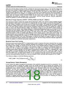
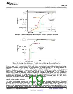
determine the IC's region of operation. Figure 28 and Figure 29 show plots of the voltage at the VSTOR pin and
the various threshold voltages for two use cases 1) when a depleted battery on VBAT_SEC is attached and the
charger enters cold start and 2) when a battery at VBAT_SEC charged above VBAT_UV is attached. For the
best operation of the system, the VBAT_OK should be used to determine when a load can be applied or
removed. A detailed description of the three voltage thresholds and the procedure for designing the external
resistors for setting the three voltage thresholds are described next.
18
Submit Documentation Feedback
Copyright © 2013–2014, Texas Instruments Incorporated
Product Folder Links :bq25505

 TI [ TEXAS INSTRUMENTS ]