bq25505
SLUSBJ3B –AUGUST 2013–REVISED JANUARY 2014
www.ti.com
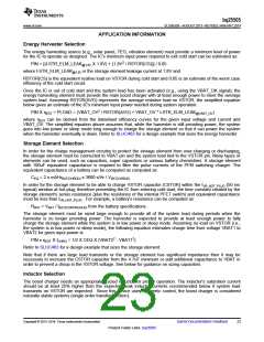
For the boost charger to operate properly, an inductor of appropriate value must be connected between
LBOOST, pin 20, and VIN_DC, pin 2. The boost charger internal control circuitry is designed to control the
switching behavior with a nominal inductance of 22 µH ± 20%. The inductor must have a peak current capability
of > 300 mA with a low series resistance (DCR) to maintain high efficiency.
A list of inductors recommended for this device is shown in Table 1.
Table 1.
Inductance (µH)
Dimensions (mm)
4.0x4.0x1.7
Part Number
LPS4018-223M
744031220
Manufacturer
Coilcraft
22
22
3.8x3.8x1.65
Wuerth
Capacitor Selection
In general, all the capacitors need to be low leakage. Any leakage the capacitors have will reduce efficiency,
increase the quiescent current and diminish the effectiveness of the IC for energy harvesting.
VREF_SAMP Capacitance
The MPPT operation depends on the sampled value of the open circuit voltage and the input regulation follows
the voltage stored on the CREF capacitor. This capacitor is sensitive to leakage since the holding period is
around 16 seconds. As the capacitor voltage drops due to any leakage, the input regulation voltage also drops
preventing proper operation from extraction the maximum power from the input source. Therefore, it is
recommended that the capacitor be an X7R or COG low leakage capacitor.
VIN_DC Capacitance
Energy from the energy harvester input source is initially stored on a capacitor, CIN, connected to VIN_DC, pin
2, and VSS, pin 1. For energy harvesters which have a source impedance which is dominated by a capacitive
behavior, the value of the harvester capacitor should scaled according to the value of the output capacitance of
the energy source, but a minimum value of 4.7 µF is recommended.
VSTOR Capacitance
Operation of the bq25505 requires two capacitors to be connected between VSTOR, pin 19, and VSS, pin 1. A
high frequency bypass capacitor of at 0.01 µF should be placed as close as possible between VSTOR and VSS.
In addition, a low ESR capacitor of at least 4.7 µF should be connected in parallel.
Additional Capacitance on VSTOR or VBAT_SEC
If there are large, fast system load transients and/or the storage element has high resistance, then the CSTOR
capacitors may momentarily discharge below the VBAT_UV threshold in response to the transient. This causes
the bq25505 to turn off the PFET switch between VSTOR and VBAT_SEC and turn on the boost charger. The
CSTOR capacitors may further discharge below the VSTOR_CHGEN threshold and cause the bq25505 to enter
Cold Start. For instance, some Li-ion batteries or thin-film batteries may not have the current capacity to meet the
surge current requirements of an attached low power radio. To prevent VSTOR from drooping, either increasing
the CSTOR capacitance or adding additional capacitance in parallel with the storage element is recommended.
For example, if boost charger is configured to charge the storage element to 4.2 V and a 500 mA load transient
of 50 µs duration infrequently occurs, then, solving I = C x dv/dt for CSTOR gives:
CSTOR ≥ 500 mA x 50 µs/(4.2 V – 1.8 V) = 10.5 µF
(5)
Note that increasing CSTOR is the recommended solution but will cause the boost charger to operate in the less
efficient cold start mode for a longer period at startup compared to using CSTOR = 4.7 µF. If longer cold start run
times are not acceptable, then place the additional capacitance in parallel with the storage element.
For a recommended list of standard components, see the EVM User’s guide (SLUUAA8).
24
Submit Documentation Feedback
Copyright © 2013–2014, Texas Instruments Incorporated
Product Folder Links :bq25505

 TI [ TEXAS INSTRUMENTS ]