bq24735
SLUSAK9 –SEPTEMBER 2011
www.ti.com
These devices have limited built-in ESD protection. The leads should be shorted together or the device placed in conductive foam
during storage or handling to prevent electrostatic damage to the MOS gates.
DEVICE INFORMATION
Q6
BSS138W
Reverse
Input
Protection
U2
IMD2A
R12
1M
EN
R13
3.01M
D2
BAT54C
Q1 (ACFET)
FDS6680A
Q2 (RBFET)
FDS6680A
RAC 10m?
SYSTEM
Adapter +
Adapter -
C17
2200pF
C16
0.1µF
Ri
2?
*
Total
Csys
R9
10 Ω
*
C1
0.1µF
C3
0.1µF
Ci
2.2µF
220µF
*
C5
1µF
ACN
VCC
C2
0.1µF
R6
4.02 kW
R10
4.02 kW
R11
4.02 kW
BATDRV
Q5 (BATFET)
FDS6680A
ACP
C15
0.01µF
C6
1µF
CMSRC
ACDRV
REGN
BTST
D1
BAT54
R1
430 kW
C9
10uF
C8
10uF
ACDET
ILIM
R2
66.5 kW
Q3
Sis412DN
HIDRV
PHASE
R8
100 kW
RSR
10m?
C7
0.047µF
U1
bq24735
R7
316 kW
Pack +
L1
4.7µH
Q4
Sis412DN
C10
10µF
C11
10µF
+3.3V
R3
10 kW
R4
10 kW
R5
10 kW
LODRV
GND
Pack -
SDA
HOST
SMBus
SCL
SRP
SRN
Dig I/O
ADC
R14
*
ACOK
IOUT
C13
0.1µF
10 Ω
PowerPad
C14
0.1µF
R15
*
C4
100 pF
7.5 W
Dig I/O
EN
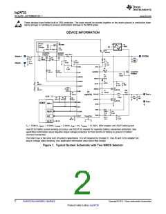
Fs = 750kHz, IADPT = 4.096A, ICHRG = 2.944A, ILIM = 4A, VCHRG = 12.592V, 90W adapter and 3S2P battery pack
Use 0Ω for better current sensing accuracy, use 10Ω/7.5Ω resistor for reversed battery connection protection. See
application information about negative output voltage protection for hard shorts on battery to ground or battery
reversed connection.
The total Csys is the lump sum of system capacitance. It is not required by charger IC. Use Ri and Ci for adapter hot
plug-in voltage spike damping. See application information about input filter design.
Figure 1. Typical System Schematic with Two NMOS Selector
2
Submit Documentation Feedback
Copyright © 2011, Texas Instruments Incorporated
Product Folder Link(s) :bq24735

 TI [ TEXAS INSTRUMENTS ]