bq24735
www.ti.com
SLUSAK9 –SEPTEMBER 2011
ELECTRICAL CHARACTERISTICS (continued)
4.5 V ≤ VVCC ≤ 24 V, 0°C ≤ TJ ≤ 125°C, typical values are at TA = 25°C, with respect to GND (unless otherwise noted)
PARAMETER
TEST CONDITIONS
MIN
TYP
MAX UNIT
ANALOG INPUT (ACDET, ILIM)
IIN_ LEAK
Input bias current
V = 7 V
–1
1
μA
PWM OSCILLATOR
FSW
PWM switching frequency
PWM increase frequency
PWM decrease frequency
ChargeOption () bit [9] = 0 (Default)
ChargeOption() bit [10:9] = 11
ChargeOption() bit [10:9] = 01
600
665
465
750
885
615
900
1100
765
kHz
kHz
kHz
FSW+
FSW–
BATFET GATE DRIVER (BATDRV)
IBATFET
BATDRV charge pump current limit
40
60
µA
VBATFET
Gate drive voltage on BATFET
VBATDRV - VSRN when VSRN > UVLO
5.5
6.1
6.5
7.4
V
Minimum load resistance between
BATDRV and SRN
RBATDRV_LOAD
RBATDRV_OFF
500
5
kΩ
kΩ
BATDRV turn-off resistance
I = 30 µA
6.2
ACFET GATE DRIVER (ACDRV)
IACFET
ACDRV charge pump current limit
40
60
μA
VACFET
Gate drive voltage on ACFET
V
ACDRV–VCMSRC when VVCC> UVLO
5.5
6.1
6.5
7.4
V
Minimum load resistance between ACDRV
and CMSRC
RACDRV_LOAD
RACDRV_OFF
VACFET_LOW
500
5
kΩ
kΩ
V
ACDRV turn-off resistance
I = 30 µA
6.2
5.9
ACDRV Turn-Off when Vgs voltage is low
(Specified by design)
PWM HIGH SIDE DRIVER (HIDRV)
RDS_HI_ON High side driver turn-on resistance
RDS_HI_OFF
V
V
V
BTST – VPH = 5.5 V, I = 10 mA
6
10
Ω
Ω
High side driver turn-off resistance
BTST – VPH = 5.5 V, I = 10 mA
0.65
1.3
Bootstrap refresh comparator threshold
voltage
BTST – VPH when low side refresh pulse is requested
VBTST_REFRESH
3.85
4.3
4.7
V
PWM LOW SIDE DRIVER (LODRV)
RDS_LO_ON Low side driver turn-on resistance
RDS_LO_OFF Low side driver turn-off resistance
PWM DRIVER TIMING
tLOW_HIGH Driver dead time from low side to high side
tHIGH_LOW Driver dead time from high side to low side
INTERNAL SOFT START
ISTEP Soft start current step
tSTEP Soft start current step time
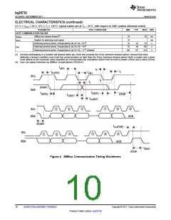
SMBus TIMING CHARACTERISTICS
VREGN = 6 V, I = 10 mA
VREGN = 6 V, I = 10 mA
7.5
0.9
12
Ω
Ω
1.4
20
20
ns
ns
64
mA
In CCM mode 10mΩ current sensing resistor
240
μs
tR
SCLK/SDATA rise time
1
300
50
μs
ns
μs
μs
μs
μs
ns
ns
µs
μs
kHz
tF
SCLK/SDATA fall time
tW(H)
SCLK pulse width high
4
4.7
4.7
4
tW(L)
SCLK Pulse Width Low
Setup time for START condition
tSU(STA)
tH(STA)
tSU(DAT)
tH(DAT)
tSU(STOP)
t(BUF)
FS(CL)
START condition hold time after which first clock pulse is generated
Data setup time
250
300
4
Data hold time
Setup time for STOP condition
Bus free time between START and STOP condition
Clock Frequency
4.7
10
100
Copyright © 2011, Texas Instruments Incorporated
Submit Documentation Feedback
9
Product Folder Link(s) :bq24735

 TI [ TEXAS INSTRUMENTS ]