bq24707
bq24707A
SLUSA78B –JULY 2010–REVISED MARCH 2011
www.ti.com
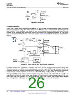
Inductor Short, MOSFET Short Protection
The IC has a unique short circuit protection feature. Its cycle-by-cycle current monitoring feature is achieved
through monitoring the voltage drop across RDS(on) of the MOSFETs after a certain amount of blanking time. In
case of MOSFET short or inductor short circuit, the over current condition is sensed by two comparators and two
counters will be triggered. After seven times of short circuit events, the charger will be latched off. To reset the
charger from latch-off status, the IC VCC pin must be pulled down below UVLO or ACDET pin must be pulled
down below 0.6V. This can be achieved by removing the adapter and shut down the operation system. The low
side MOSFET short circuit voltage drop threshold is fixed to typical 110mV. The high side MOSFET short circuit
voltage drop threshold can be adjusted via SMBus command. ChargeOption() bit[8:7] = 00, 01, 10, 11 set the
threshold 300mV, 500mV, 700mV and 900mV respectively.
Due to the certain amount of blanking time to prevent noise when MOSFET just turns on, the cycle-by-cycle
charge over-current protection may detect high current and turn off MOSFET first before the short circuit
protection circuit can detect short condition because the blanking time has not finished. In such a case the
charge may not be able to detect shorts circuit and counter may not be able to count to seven then latch off.
Instead the charge may continuously keep switching with very narrow duty cycle to limit the cycle-by-cycle
current peak value. However, the charger should still be safe and will not cause failure because the duty cycle is
limited to a very short of time and MOSFET should be still inside the safety operation area. During a soft start
period, it may takes long time instead of just seven switching cycles to detect short circuit based on the same
blanking time reason.
Independent Comparator
The IC has an independent comparator can be used to compare input current, charge current or battery voltage
with internal reference . Program CMPIN voltage by connecting a resistor divider from IOUT pin to CMPIN pin to
GND pin for adapter or charge current comparison or from SRN pin to CMPIN pin to GND pin for battery voltage
comparison. When CMPIN is above internal reference, CMPOUT is pulled to external pull up rail by external pull
up resistor. When CMPIN is below internal reference, CMPOUT is pulled to GND by internal MOSFET. Place a
resistor between CMPIN and CMPOUT to program hysteresis. The internal reference can be set to 0.6V or 2.4V
via SMBus command (ChargeOption() bit[4]=0 set internal reference 0.6V, bit[4]=1 set 2.4V).
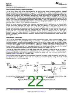
There is one 50kΩ series resistor RS and one 2000kΩ pull down resistor RDOWN for CMPIN pin as shown in
Figure 19. To get the accurate comparison set point, these two resistors must be included in the calculation. A
spreadsheet calculation tool has been developed to simplify the design work. User can down load from the TI
Web site at www.ti.com under the IC product folder.
Figure 19 also shows one application circuit using this comparator for battery voltage comparison. After using the
superposition principle and fill the components value into the spreadsheet the battery voltage threshold is 9.45V
for rising edge and 8.99V for falling edge.
3.3V
RHYS
3010kΩ
RUP
10kΩ
VBAT
CMPIN
RTOP
422kΩ
CMPOUT
RDOWN
2000kΩ
RS
50kΩ
CMPIN
RS
CMPOUT
RDOWN
2000kΩ
RBOT
30.1kΩ
50kΩ
0.6V/2.4V
0.6V
(a) Internal Circuit showing the series resistor and
pull down resistor
(b) Application Circuit, 9.45V rising edge and 8.99V falling edge
for 3cell battery
Figure 19. IC Comparator Internal Circuit and Application Circuit
22
Submit Documentation Feedback
© 2010–2011, Texas Instruments Incorporated
Product Folder Link(s): bq24707 bq24707A

 TI [ TEXAS INSTRUMENTS ]