bq24707
bq24707A
www.ti.com
SLUSA78B –JULY 2010–REVISED MARCH 2011
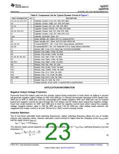
Table 8. Component List for Typical System Circuit of Figure 1
PART DESIGNATOR
QTY
5
DESCRIPTION
Capacitor, Ceramic, 0.1µF, 25V, 10%, X7R, 0603
C1, C2, C3, C13, C14
C4
1
Capacitor, Ceramic, 100pF, 25V, 10%, X7R, 0603
Capacitor, Ceramic, 1µF, 25V, 10%, X7R, 0603
Capacitor, Ceramic, 0.047µF, 25V, 10%, X7R, 0603
Capacitor, Ceramic, 10µF, 25V, 10%, X7R, 1206
Capacitor, Ceramic, 2.2µF, 25V, 10%, X7R, 1210
Capacitor, Electrolytic, 220µF, 25V
C5, C6
2
C7
1
C8, C9, C10, C11
4
Ci
1
Csys
1
D1
1
Diode, Schottky, 30V, 200mA, SOT-23, Fairchild, BAT54
Diode, Schottky, 40V, 120mA, SOD-323, NXP, RB751V40
P-channel MOSFET, –30V, –9.4A, SO-8, Vishay Siliconix, Si4435DDY
N-channel MOSFET, 30V, 12A, PowerPAK 1212-8, Vishay Siliconix, SiS412DN
Inductor, SMT, 4.7µH, 5.5A, Vishay Dale, IHLP2525CZER4R7M01
Resistor, Chip, 430kΩ, 1/10W, 1%, 0603
D2
1
Q1, Q2, Q5
3
Q3, Q4
2
L1
1
R1
1
R2
1
Resistor, Chip, 66.5kΩ, 1/10W, 1%, 0603
R3, R4, R5, R6, R10
5
Resistor, Chip, 10kΩ, 1/10W, 1%, 0603
R7
1
Resistor, Chip, 316kΩ, 1/10W, 1%, 0603
R8, R12
R9
2
Resistor, Chip, 100kΩ, 1/10W, 1%, 0603
1
Resistor, Chip, 10Ω, 1/4W, 1%, 1206
R11
1
Resistor, Chip, 39.2kΩ, 1/10W, 1%, 0603
R13
1
Resistor, Chip, 3.01MΩ, 1/10W, 1%, 0603
R14
1
Resistor, Chip, 10 Ω, 1/10W, 5%, 0603
R15
1
Resistor, Chip, 7.5 Ω, 1/10W, 5%, 0603
RAC, RSR
Ri
2
Resistor, Chip, 0.01Ω, 1/2W, 1%, 1206
1
Resistor, Chip, 2Ω, 1/2W, 1%, 1210
U1
1
Charger controller, 20 pin VQFN, TI, bq24707RGR or bq24707ARGR
APPLICATION INFORMATION
Negative Output Voltage Protection
Reversely insert the battery pack into the charger output during production or hard shorts on battery to ground
will generate negative output voltage on SRP and SRN pin. IC internal electrostatic-discharge (ESD) diodes from
GND pin to SRP or SRN pins and two anti-parallel (AP) diodes between SRP and SRN pins can be forward
biased and negative current can pass through the ESD diodes and AP diodes when output has negative voltage.
Insert two small resistors for SRP and SRN pins to limit the negative current level when output has negative
voltage. Suggest resistor value is 10Ω for SRP pin and 7-8Ω for SRN pin. After adding small resistors, the
suggested pre-charge current is at least 192mA for a 10mΩ current sensing resistor.
Inductor Selection
The IC has three selectable fixed switching frequencies. Higher switching frequency allows the use of smaller
inductor and capacitor values. Inductor saturation current should be higher than the charging current (ICHG) plus
half the ripple current (IRIPPLE):
ISAT ³ ICHG + (1/2) IRIPPLE
(4)
The inductor ripple current depends on input voltage (VIN), duty cycle (D = VOUT/VIN), switching frequency (fS) and
inductance (L):
V
´ D ´ (1 - D)
IN
IRIPPLE
=
fS ´ L
(5)
© 2010–2011, Texas Instruments Incorporated
Submit Documentation Feedback
23
Product Folder Link(s): bq24707 bq24707A

 TI [ TEXAS INSTRUMENTS ]