bq20z45
www.ti.com .................................................................................................................................................................................................. SLUS800–MARCH 2009
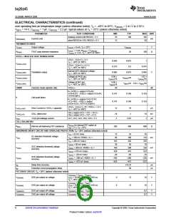
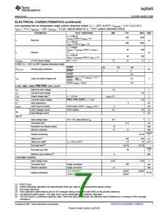
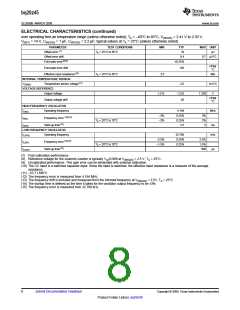
ELECTRICAL CHARACTERISTICS (continued)
over operating free-air temperature range (unless otherwise noted), TA = –40°C to 85°C, V(REG25) = 2.41 V to 2.59 V,
V(BAT) = 14 V, C(REG25) = 1 µF, C(REG33) = 2.2 µF; typical values at TA = 25°C (unless otherwise noted)
PARAMETER
TEST CONDITIONS
MIN
TYP
MAX UNIT
CL= 4700 pF;
400
1000
µs
V(PACK) ≤ DSG ≤ V(PACK) + 4V
tr
Rise time
CL= 4700 pF;
400
40
1000
V(BAT) ≤ CHG ≤ V(BAT) + 4V
CL= 4700pF;
V(PACK) + V(DSGON) ≤ DSG ≤ V(PACK)
+
200
1V
tf
Fall time
µs
CL= 4700 pF;
V(BAT) + V(CHGON) ≤ CHG ≤ V(BAT) + 1V
40
200
V(ZVCHG)
ZVCHG clamp voltage
BAT = 4.5 V
3.3
3.5
3.7
V
LOGIC; TA = –40°C to 100°C (unless otherwise noted)
ALERT
RESET
ALERT
60
1
100
3
200
6
R(PULLUP)
Internal pullup resistance
kΩ
0.2
RESET; V(BAT) = 7V; V(REG25) = 1.5 V;
I(RESET) = 200 µA
VOL
Logic low output voltage level
0.4
0.6
V
GPOD; I(GPOD) = 50 µA
LOGIC SMBC, SMBD, PFIN, PRES, SAFE, ALERT
VIH
High-level input voltage
Low-level input voltage
Output voltage high(1)
Low-level output voltage
Input capacitance
2.0
V
V
VIL
0.8
0.4
VOH
VOL
CI
IL = –0.5 mA
VREG25–0.5
V
PRES, PFIN, ALERT, IL = 7 mA;
V
5
pF
mA
µA
µA
I(SAFE)
SAFE source currents
SAFE leakage current
Input leakage current
SAFE active, SAFE = V(REG25) –0.6 V
SAFE inactive
–3
–0.2
0.2
1
Ilkg
ADC(2)
Input voltage range
Conversion time
TS1, TS2, using Internal Vref
–0.2
1
V
31.5
15
ms
bits
bits
Resolution (no missing codes)
Effective resolution
16
14
%FSR(
Integral nonlinearity
±0.03
250
3)
Offset error(4)
Offset error drift(4)
Full-scale error(5)
140
2.5
µV
TA = 25°C to 85°C
18 µV/°C
±0.7%
±0.1%
PPM/
°C
Full-scale error drift
50
Effective input resistance(6)
8
–0.20
15
MΩ
COULOMB COUNTER
Input voltage range
0.20
V
Conversion time
Single conversion
Single conversion
–0.1 V to 0.20 V
–0.20 V to –0.1 V
250
ms
bits
Effective resolution
±0.007
±0.007
±0.034
Integral nonlinearity
%FSR
(1) RC[0:7] bus
(2) Unless otherwise specified, the specification limits are valid at all measurement speed modes
(3) Full-scale reference
(4) Post-calibration performance and no I/O changes during conversion with SRN as the ground reference
(5) Uncalibrated performance. This gain error can be eliminated with external calibration.
(6) The A/D input is a switched-capacitor input. Since the input is switched, the effective input resistance is a measure of the average
resistance.
Copyright © 2009, Texas Instruments Incorporated
Submit Documentation Feedback
7
Product Folder Link(s): bq20z45

 TI [ TEXAS INSTRUMENTS ]