bq20z45
www.ti.com .................................................................................................................................................................................................. SLUS800–MARCH 2009
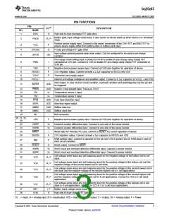
PIN FUNCTIONS
PIN
I/O(1)
DESCRIPTION
NO.
NAME
1
DSG
O
High side N-chan discharge FET gate drive
Battery pack input voltage sense input. It also serves as device wake up when device is in shutdown
mode.
2
PACK
IA, P
Positive device supply input. Connect to the center connection of the CHG FET and DSG FET to
ensure device supply either from battery stack or battery pack input
3
4
5
VCC
P
O
ZVCHG
GPOD
P-chan pre-charge FET gate drive
High voltage general purpose open drain output. Can be configured to be used in pre-charge
condition
OD
Pre-charge mode setting input. Connect to PACK to enable 0v pre-charge using charge FET
connected at CHG pin. Connect to VSS to disable 0V pre-charge using charge FET connected at
CHG pin.
6
PMS
I
7
8
VSS
REG33
TOUT
P
P
P
-
Negative device power supply input. Connect all VSS pins together for operation of device
3.3V regulator output. Connect at least a 2.2µF capacitor to REG33 and VSS
Thermistor bias supply output
9
10
VCELL+
Internal cell voltage multiplexer and amplifier output. Connect a 0.1µF capacitor to VCELL+ and VSS
Alert output. In case of short circuit condition, overload condition and watchdog time out this pin will
be triggered.
11
ALERT
I/OD
12
13
14
15
16
17
18
19
PRES
TS1
I/OD
IA
System / Host present input. Pull up to TOUT
Temperature sensor 1 input
Temperature sensor 2 input
Fuse blow detection input
blow fuse signal output
SMBus data line
TS2
IA
PFIN
SAFE
SMBD
SMBC
NC
I/OD
I/OD
I/OD
I/OD
-
SMBus clock line
Not connected
20, 21, 25,
28
VSS
P
Negative device power supply input. Connect all VSS pins together for operation of device
22
23
24
26
GSRP
GSRN
MRST
REG25
IA
IA
I
Coulomb counter differential input. Connect to one side of the sense resistor
Coulomb counter differential input. Connect to one side of the sense resistor
Reset input for internal CPU core. connect to RESET for correct operation of device
2.5V regulator output. Connect at least a 1µF capacitor to REG25 and VSS
P
RAM backup input. Connect a capacitor to this pin and VSS to protect loss of RAM data in case of
short circuit condition
27
RBI
P
29
30
31
RESET
ASRN
ASRP
O
IA
IA
Reset output. Connect to MSRT.
Short circuit and overload detection differential input. Connect to sense resistor
Short circuit and overload detection differential input. Connect to sense resistor
Cell voltage sense input and cell balancing input for the negative voltage of the bottom cell in cell
stack.
32
33
34
VC5
VC4
VC3
IA, P
IA, P
IA, P
Cell voltage sense input and cell balancing input for the positive voltage of the bottom cell and the
negative voltage of the second lowest cell in cell stack.
Cell voltage sense input and cell balancing input for the positive voltage of the second lowest cell in
cell stack and the negative voltage of the second highest cell in 4 cell applications.
Cell voltage sense input and cell balancing input for the positive voltage of the second highest cell
35
36
VC2
VC1
IA, P and the negative voltage of the highest cell in 4 cell applications. Connect to VC3 in 2 cell stack
applications
Cell voltage sense input and cell balancing input for the positive voltage of the highest cell in cell
IA, P
stack in 4 cell applications. Connect to VC2 in 3 or 2 cell stack applications
37
38
BAT
I, P
O
Battery stack voltage sense input
CHG
High side N-chan charge FET gate drive
(1) I = Input, IA = Analog input, I/O = Input/output, I/OD = Input/Open-drain output, O = Output, OA = Analog output, P = Power
Copyright © 2009, Texas Instruments Incorporated
Submit Documentation Feedback
3
Product Folder Link(s): bq20z45

 TI [ TEXAS INSTRUMENTS ]