bq20z45
www.ti.com .................................................................................................................................................................................................. SLUS800–MARCH 2009
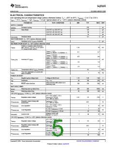
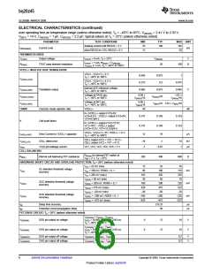
DATA FLASH CHARACTERISTICS OVER RECOMMENDED OPERATING TEMPERATURE AND
SUPPLY VOLTAGE
Typical Values at TA = 25°C and V(REG25) = 2.5 V (unless otherwise noted)
PARAMETER
Data retention
Flash programming write-cycles
t(ROWPROG) Row programming time
TEST CONDITIONS
MIN TYP MAX
UNIT
Years
Cycles
ms
10
20k
2
(1)
See
t(MASSERASE) Mass-erase time
t(PAGEERASE) Page-erase time
200
20
ms
ms
I(DDPROG)
I(DDERASE)
RAM BACKUP
Flash-write supply current
5
5
10
10
mA
Flash-erase supply current
mA
V(RBI) > V(RBI)MIN , VREG25 < VIT–, TA = 85°C
V(RBI) > V(RBI)MIN , VREG25 < VIT–, TA = 25°C
1000 2500
90 220
I(RB)
RB data-retention input current
RB data-retention input voltage(1)
nA
V
V(RB)
1.7
(1) Specified by design. Not production tested.
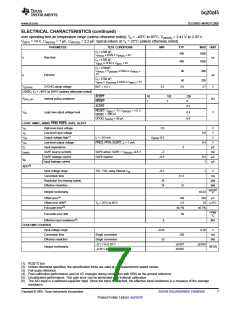
SMBus TIMING CHARACTERISTICS
TA = –40°C to 85°C Typical Values at TA = 25°C and VREG25 = 2.5 V (Unless Otherwise Noted)
PARAMETER
TEST CONDITIONS
MIN
TYP
MAX
UNIT
f(SMB)
f(MAS)
SMBus operating frequency
Slave mode, SMBC 50% duty cycle
10
100
kHz
Master mode, No clock low slave
extend
SMBus master clock frequency
51.2
kHz
µs
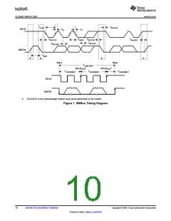
Bus free time between start and stop
(see Figure 1)
t(BUF)
4.7
t(HD:STA)
t(SU:STA)
t(SU:STO)
Hold time after (repeated) start (see Figure 1)
Repeated start setup time (see Figure 1)
Stop setup time (see Figure 1)
4
4.7
4
µs
µs
µs
ns
Receive mode
Transmit mode
0
t(HD:DAT)
Data hold time (see Figure 1)
300
250
25
4.7
4
t(SU:DAT)
t(TIMEOUT)
t(LOW)
Data setup time (see Figure 1)
Error signal/detect (see Figure 1)
Clock low period (see Figure 1)
Clock high period (see Figure 1)
ns
µs
µs
µs
ms
(1)
See
35
(2)
t(HIGH)
See
50
25
(3)
t(LOW:SEXT) Cumulative clock low slave extend time
See
Cumulative clock low master extend time
(see Figure 1)
(4)
t(LOW:MEXT)
See
10
ms
(5)
tf
tr
Clock/data fall time
Clock/data rise time
See
300
ns
ns
(6)
See
1000
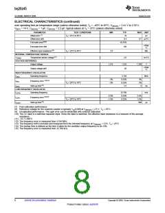
(1) The bq8040 times out when any clock low exceeds t(TIMEOUT)
.
(2) t(HIGH), Max, is the minimum bus idle time. SMBC = SMBD = 1 for t > 50 ms causes reset of any transaction involving bq8040 that is in
progress. This specification is valid when the NC_SMB control bit remains in the default cleared state (CLK[0]=0).
(3) t(LOW:SEXT) is the cumulative time a slave device is allowed to extend the clock cycles in one message from initial start to the stop.
(4) t(LOW:MEXT) is the cumulative time a master device is allowed to extend the clock cycles in one message from initial start to the stop.
(5) Rise time tr = VILMAX – 0.15) to (VIHMIN + 0.15)
(6) Fall time tf = 0.9VDD to (VILMAX – 0.15)
Copyright © 2009, Texas Instruments Incorporated
Submit Documentation Feedback
9
Product Folder Link(s): bq20z45

 TI [ TEXAS INSTRUMENTS ]