bq2031
Configuring Algorithm and Display
Modes
V
CC
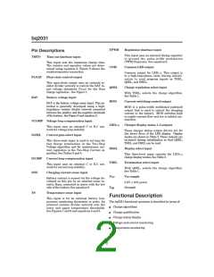
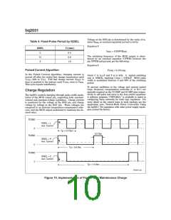
QSEL/LED3, DSEL/LED2, and TSEL/LED1 are bi-
directional pins with two functions; they are LED driver
pins as outputs and programming pins for the bq2031 as
inputs. The selection of pull-up, pull-down, or no pull re-
sistor programs the charging algorithm on QSEL and
TSEL per Table 1 and the display mode on DSEL per
Table 2. The bq2031 latches the program states when
any of the following events occurs:
BAT +
RB1
RB2
2
3
FLOAT
BAT
RB3
13
V
CC
12
V
SS
1.
VCC rises to a valid level.
BAT -
2. The bq2031 leaves the Fault state.
3. The bq2031 detects battery insertion.
7
SNS
bq2031
R
SNS
The LEDs go blank for approximately 750ms (typical)
while new programming data is latched.
V
SS
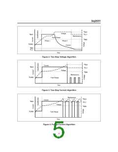
For example, Figure 5 shows the bq2031 configured for
the Pulsed Current algorithm and display mode 2.
FG203102.eps
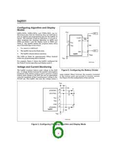
Voltage and Current Monitoring
The bq2031 monitors battery pack voltage at the BAT
pin. A voltage divider between the positive and negative
terminals of the battery pack is used to present a scaled
battery pack voltage to the BAT pin and an appropriate
value for regulation of float (maintenance) voltage to the
FLOAT pin. The bq2031 also uses the voltage across a
Figure 6. Configuring the Battery Divider
sense resistor (RSNS) between the negative terminal
of the battery pack and ground to monitor current.
See Figure 6 for the configuration of this network.
V
CC
10K
10K
1K
16
LED2/DSEL
LED1/TSEL
15
1K
13
12
V
CC
V
SS
11
10
COM
LED3/QSEL
1K
bq2031
10K
V
SS
FG203103.eps
Figure 5. Configuring Charging Algorithm and Display Mode
6

 TI [ TEXAS INSTRUMENTS ]