bq2031
n
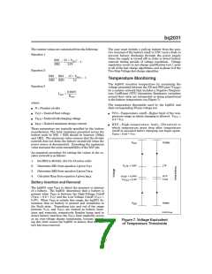
LTF—Low-temperature fault—Lower limit of the
temperature range in which charging is allowed. VLTF
= 0.6 VCC
*
V
CC
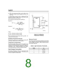
A resistor-divider network must be implemented that
presents the defined voltage levels to the TS pin at the
desired temperatures (see Figure 8).
RT1
bq2031
The equations for determining RT1 and RT2 are:
Equation 4
NTC
Thermistor
13
V
CC
12
(VCC − 0.250V)
RT1 ∗ (RT2 + RLTF
RT
t
V
SS
RT2
0.6 ∗ VCC
=
)
1 +
(RT2 ∗ RLTF
)
7
8
SNS
TS
BAT -
Equation 5
R
SNS
1
0.44 =
V
SS
RT1 ∗ (RT2 + RHTF
)
1 +
(RT2 ∗ RHTF
)
FG203105.eps
where:
n
RLTF = thermistor resistance at LTF
RHTF = thermistor resistance at HTF
Figure 8. Configuring
Temperature Sensing
n
TCO is determined by the values of RT1 and RT2. 1%
resistors are recommended.
Disabling Temperature Sensing
Minimum Current
Temperature sensing can be disabled by removing RT
and using a 100kΩ resistor for RT1 and RT2.
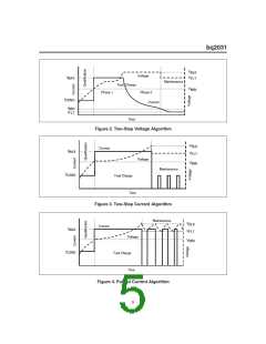
Fast charge terminates when the charging current drops
below a minimum current threshold programmed by the
value of IGSEL (see Table 3). This is used by the Two-
Step Voltage algorithm.
Temperature Compensation
The internal voltage reference used by the bq2031 for all
voltage threshold determinations is compensated for
temperature. The temperature coefficient is -3.9mV/°C,
normalized to 25°C. Voltage thresholds in the bq2031
vary by this proportion as ambient conditions change.
Table 3. IMIN Termination Thresholds
IGSEL
IMIN
Fast-Charge Termination
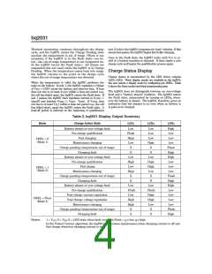
Fast-charge termination criteria are programmed with
the fast charge algorithm per Table 1. Note that not all
criteria are applied in all algorithms.
0
1
Z
IMAX/10
IMAX/20
IMAX/30
8

 TI [ TEXAS INSTRUMENTS ]