bq2031
TPWM
COM
Regulation timebase input
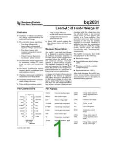
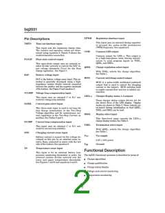
Pin Descriptions
This input uses an external timing capacitor
to ground the pulse-width modulation
(PWM) frequency. See equation 9.
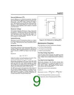
TMTO
FLOAT
BAT
Time-out timebase input
This input sets the maximum charge time.
The resistor and capacitor values are deter-
mined using equation 6. Figure 9 shows the
resistor/capacitor connection.
Common LED output
Common output for LED1–3. This output is
in a high-impedance state during initiali-
zation to read program inputs on TSEL,
QSEL, and DSEL.
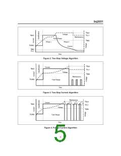
Float state control output
This open-drain output uses an external re-
sistor divider network to control the BAT in-
put voltage threshold (VFLT) for the float
charge regulation. See Figure 1.
QSEL
MOD
Charge regulation select input
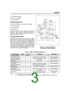
With TSEL, selects the charge algorithm.
See Table 1.
Battery voltage input
Current-switching control output
BAT is the battery voltage sense input. This po-
tential is generally developed using a high-
impedance resistor divider network connected
between the positive and the negative terminals
of the battery. See Figure 6 and equation 2.
MOD is a pulse-width modulated push/pull
output that is used to control the charging
current to the battery. MOD switches high
to enable current flow and low to inhibit cur-
rent flow.
VCOMP Voltage loop compensation input
LED1–3
Charger display status 1–3 outputs
This input uses an external C or R-C net-
work for voltage loop stability.
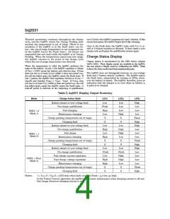
These charger status output drivers are for
the direct drive of the LED display. Display
modes are shown in Table 2. These outputs are
tri-stated during initialization so that QSEL,
TSEL, and DSEL can be read.
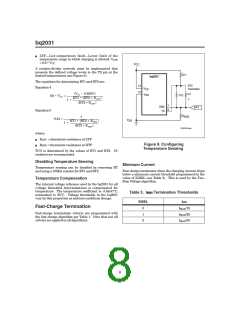
IGSEL
Current gain select input
This three-state input is used to set IMIN for
fast charge termination in the Two-Step
Voltage algorithm and for maintenance cur-
rent regulation in the Two-Step Current al-
gorithm. See Tables 3 and 4.
DSEL
TSEL
Display select input
This three-level input controls the LED1–3
charge display modes. See Table 2.
ICOMP
SNS
Current loop compensation input
Termination select input
This input uses an external C or R-C net-
work for current loop stability.
With QSEL, selects the charge algorithm.
See Table 1.
Charging current sense input
VCC
VCC supply
Battery current is sensed via the voltage de-
veloped on this pin by an external sense re-
sistor, RSNS, connected in series with the low
side of the battery. See equation 8.
5.0V, 10% power
VSS
Ground
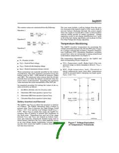
TS
Temperature sense input
Functional Description
This input is for an external battery tem-
perature monitoring thermistor or probe. An
external resistor divider network sets the
lower and upper temperature thresholds.
See Figures 7 and 8 and equations 4 and 5.
The bq2031 functional operation is described in terms of:
n
n
n
n
n
Charge algorithms
Charge qualification
Charge status display
Voltage and current monitoring
Temperature monitoring
2

 TI [ TEXAS INSTRUMENTS ]