bq2031
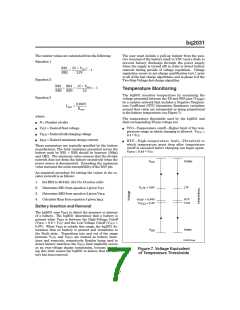
The resistor values are calculated from the following:
Equation 1
The user must include a pull-up resistor from the posi-
tive terminal of the battery stack to VDC (and a diode to
prevent battery discharge through the power supply
when the supply is turned off) in order to detect battery
removal during periods of voltage regulation. Voltage
regulation occurs in pre-charge qualification test 1 prior
to all of the fast charge algorithms, and in phase 2 of the
Two-Step Voltage fast charge algorithm.
(N ∗ VFLT
)
RB1
RB2
=
− 1
2.2V
Equation 2
Equation 3
N ∗ V
RB1 RB1
RB2 RB3
+
= (
BLK ) − 1
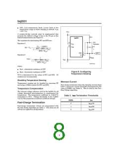
Temperature Monitoring
2.2
The bq2031 monitors temperature by examining the
voltage presented between the TS and SNS pins (VTEMP
)
by a resistor network that includes a Negative Tempera-
ture Coefficient (NTC) thermistor. Resistance variations
around that value are interpreted as being proportional
to the battery temperature (see Figure 7).
0.250V
RSNS
IMAX
=
where:
The temperature thresholds used by the bq2031 and
their corresponding TS pin voltage are:
n
n
n
n
N = Number of cells
VFLT = Desired float voltage
n
TCO—Temperature cutoff—Higher limit of the tem-
perature range in which charging is allowed. VTCO
0.4 VCC
=
VBLK = Desired bulk charging voltage
*
IMAX = Desired maximum charge current
n
HTF—High-temperature fault—Threshold to
which temperature must drop after temperature
cutoff is exceeded before charging can begin again.
These parameters are typically specified by the battery
manufacturer. The total resistance presented across the
battery pack by RB1 + RB2 should be between 150kΩ
and 1MΩ. The minimum value ensures that the divider
network does not drain the battery excessively when the
power source is disconnected. Exceeding the maximum
value increases the noise susceptibility of the BAT pin.
V
HTF = 0.44 VCC
*
V
Colder
CC
An empirical procedure for setting the values in the re-
sistor network is as follows:
1. Set RB2 to 49.9 kΩ. (for 3 to 18 series cells)
2. Determine RB1 from equation 1 given VFLT
3. Determine RB3 from equation 2 given VBLK
4. Calculate RSNS from equation 3 given IMAX
V
= 0.6V
LTF
LTF
V
= 0.44V
= 0.4V
HTF
TCO
HTF
V
TCO
Battery Insertion and Removal
The bq2031 uses VBAT to detect the presence or absence
of a battery. The bq2031 determines that a battery is
present when VBAT is between the High-Voltage Cutoff
(VHCO = 0.6 VCC) and the Low-Voltage Cutoff (VLCO
=
*
0.8V). When VBAT is outside this range, the bq2031 de-
termines that no battery is present and transitions to
the Fault state. Transitions into and out of the range
between VLCO and VHCO are treated as battery inser-
tions and removals, respectively. Besides being used to
detect battery insertion, the VHCO limit implicitly serves
as an over-voltage charge termination, because exceed-
ing this limit causes the bq2031 to believe that the bat-
tery has been removed.
V
Hotter
SS
FG203104.eps
Figure 7. Voltage Equivalent
of Temperature Thresholds
7

 TI [ TEXAS INSTRUMENTS ]