bq2011K
ternal bq2011K registers when VCC momentarily drops be-
low 3.0V. VCC is output on RBI when VCC is above 3.0V.
TMPGG (hex)
Temperature Range
< -30°C
0x
1x
2x
3x
4x
5x
6x
7x
8x
9x
Ax
Bx
Cx
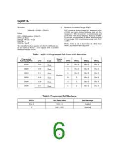
After VCC rises above 3.0V, the bq2011K checks the internal
registers for data loss or corruption. If data has changed,
then the NAC register is cleared, and the LMD register is
loaded with the initial PFC.
-30°C to -20°C
-20°C to -10°C
-10°C to 0°C
0°C to 10°C
10°C to 20°C
20°C to 30°C
30°C to 40°C
40°C to 50°C
50°C to 60°C
60°C to 70°C
70°C to 80°C
> 80°C
Voltage Thresholds
In conjunction with monitoring VSR for charge/discharge
currents, the bq2011K monitors the single-cell battery po-
tential through the SB pin. The single-cell voltage poten-
tial is determined through a resistor-divider network per
the following equation:
RB1
RB2
= N − 1
where N is the number of cells, RB1 is connected to the
positive battery terminal, and RB2 is connected to the
negative battery terminal. The single-cell battery volt-
age is monitored for the end-of-discharge voltage (EDV)
and for maximum cell voltage (MCV). The EDV thresh-
old level is used to determine when the battery has
reached an “empty” state, and the MCV threshold is used
for fault detection during charging. The MCV threshold
for the bq2011K is fixed at:
Layout Considerations
The bq2011K measures the voltage differential between
the SR and VSS pins. VOS (the offset voltage at the SR
pin) is greatly affected by PC board layout. For optimal
results, the PC board layout should follow the strict rule of
a single-point ground return. Sharing high-current
ground with small signal ground causes undesirable noise
on the small signal nodes. Additionally:
V
MCV = 2.00V
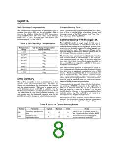
The EDV threshold varies as a function of discharge cur-
rent as follows:
ꢀ
The capacitors (SB and VCC) should be placed as
close as possible to the SB and VCC pins, respectively,
and their paths to VSS should be as short as possible.
A high-quality ceramic capacitor of 0.1µf is
VSRO (mV)
0 < VSRO ≤ 10
10 < VSRO ≤ 20
20 < VSRO ≤ 40
40 < VSRO ≤ 60
VSRO > 60
VEDV (V)
1.160
1.124
1.060
0.960
recommended for VCC
.
ꢀ
ꢀ
The sense resistor (RS) should be as close as possible
to the bq2011K.
0 (OVLD)
The R-C on the SR pin should be located as close as
possible to the SR pin. The maximum R should not
exceed 20K.
Reset
Reset can be accomplished with a command over the se-
rial port as described on page 13.
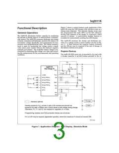
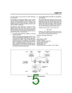
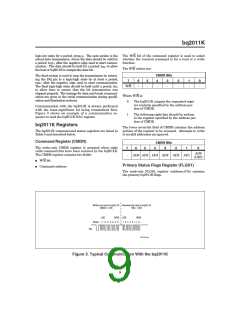
Gas Gauge Operation
The operational overview diagram in Figure 2 illus-
trates the operation of the bq2011K. The bq2011K accu-
mulates a measure of charge and discharge currents, as
well as an estimation of self-discharge. Charge currents
are temperature and rate compensated, whereas self-
discharge is only temperature compensated.
Temperature
The bq2011K internally determines the temperature in
10°C steps centered from -35°C to +85°C. The tempera-
ture steps are used to adapt charge and discharge rate
compensations, self-discharge counting, and available
charge display translation. The temperature range is
available over the serial port in 10°C increments as
shown below:
The main counter, Nominal Available Charge (NAC),
represents the available battery capacity at any given
time. Battery charging increments the NAC register,
while battery discharging and self-discharge decrement
4

 TI [ TEXAS INSTRUMENTS ]