bq2011K
No connect
NC
Pin Descriptions
Display control input
DISP
LED common
LCOM
DISP floating allows the LED display to
be active during certain charge and dis-
charge conditions. Transitioning DISP
low activates the display for 4 0.5 seconds.
Open-drain output switches VCC to source cur-
rent for the LEDs. The switch is off during ini-
tialization to allow reading of PROG1-4 pull-up
or pull-down program resistors. LCOM is high
impedance when the display is off.
Secondary battery input
SB
LED display segment outputs
SEG1–
SEG5
This input monitors the single-cell voltage
potential through a high-impedance resis-
tive divider network for the end-of-discharge
voltage (EDV) threshold and maximum cell
voltage (MCV).
Each output may activate an LED to sink
the current sourced from LCOM, the battery,
or VCC
.
Programmed full count selection inputs
(dual function with SEG1 - SEG4)
PROG1–
PROG4
Register backup input
RBI
This input is used to provide backup poten-
tial to the bq2011K registers during periods
when VCC < 3V. A storage capacitor should
be connected to RBI.
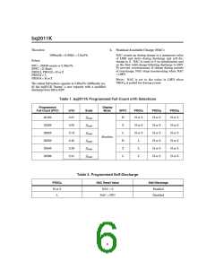
These three-level input pins define the pro-
grammed full count (PFC) in conjunction
with SPFC pin, define the display mode and
enable or disable self-discharge.
Serial I/O pin
DQ
Programmed full count selection input
SPFC
This is an open-drain bidirectional pin.
Voltage reference output for regulator
This three-level input pin along with PROG1-3
define the programmed full count (PFC)
thresholds described in Table 1. The state of
the SPFC pin is only read immediately after
a reset condition.
REF
REF provides a voltage reference output for
an optional micro-regulator.
Sense resistor input
SR
Supply voltage input
Ground
VCC
VSS
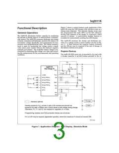
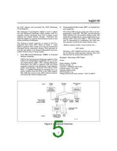
The voltage drop (VSR) across the sense re-
sistor RS is monitored and integrated over
time to interpret charge and discharge activ-
ity. The SR input is tied to the low side of
the sense resistor and battery pack ground
(see Figure 1). VSR > VSS indicates discharge,
and VSR < VSS indicates charge. The effec-
tive voltage drop, VSRO, as seen by the
bq2011K is VSR + VOS (see Table 4).
2

 TI [ TEXAS INSTRUMENTS ]