bq2011K
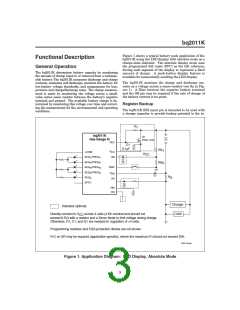
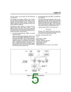
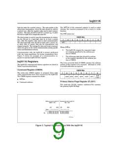
Figure 1 shows a typical battery pack application of the
bq2011K using the LED display with absolute mode as a
charge-state indicator. The absolute display mode uses
the programmed full count (PFC) as the full reference,
forcing each segment of the display to represent a fixed
amount of charge. A push-button display feature is
available for momentarily enabling the LED display.
Functional Description
General Operation
The bq2011K determines battery capacity by monitoring
the amount of charge input to or removed from a recharge-
able battery. The bq2011K measures discharge and charge
currents, estimates self-discharge, monitors the battery for
low-battery voltage thresholds, and compensates for tem-
perature and charge/discharge rates. The charge measure-
ment is made by monitoring the voltage across a small-
value series sense resistor between the battery’s negative
terminal and ground. The available battery charge is de-
termined by monitoring this voltage over time and correct-
ing the measurement for the environmental and operating
conditions.
The bq2011K monitors the charge and discharge cur-
rents as a voltage across a sense resistor (see RS in Fig-
ure 1). A filter between the negative battery terminal
and the SR pin may be required if the rate of change of
the battery current is too great.
Register Backup
The bq2011K RBI input pin is intended to be used with
a storage capacitor to provide backup potential to the in-
R
1
bq2011K
Q1
Gas Gauge IC
ZVNL110A
REF
C1
0.1 F
RB
RB
1
V
LCOM
CC
V
CC
SEG /PROG
1
SB
1
2
3
4
SEG /PROG
2
2
DISP
SEG /PROG
3
SEG /PROG
4
V
SS
R
S
SEG
5
SR
SPFC
RBI
DQ
Charger
Load
Indicates optional.
Directly connect to V
CC
across 4 cells (4.8V nominal and should not
exceed 6.5V) with a resistor and a Zener diode to limit voltage during charge.
Otherwise, R1, C1, and Q1 are needed for regulation of >4 cells.
Programming resistors and ESD-protection diodes are not shown.
R-C on SR may be required (application-specific), where the maximum R should not exceed 20K.
FG201103.eps
Figure 1. Application Diagram: LED Display, Absolute Mode
3

 TI [ TEXAS INSTRUMENTS ]