bq2011K
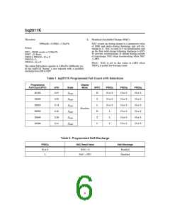
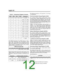
Self-Discharge Compensation
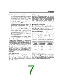
Current-Sensing Error
The self-discharge compensation is programmed for a
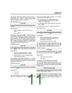
Table 4 illustrates the current-sensing error as a func-
tion of VSR. A digital filter eliminates charge and
1
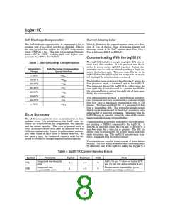
nominal rate of
NAC per day or disabled. This is
80
*
the rate for a battery within the 20–30°C temperature
range (TMPGG = 6x). This rate varies across 8 ranges
from <10°C to >70°C, doubling with each higher tem-
perature step (10°C). See Table 3.
discharge counts to the NAC register when VSRO (VSR
OS) is between -400µV and 500µV.
+
V
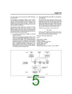
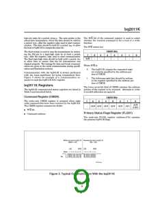
Communicating With the bq2011K
The bq2011K includes a simple single-pin (DQ plus re-
turn) serial data interface. A host processor uses the in-
terface to access various bq2011K registers. Battery char-
acteristics may be easily monitored by adding a single con-
tact to the battery pack. The open-drain DQ pin on the
bq2011K should be pulled up by the host system, or may be
left floating if the serial interface is not used.
Table 3. Self-Discharge Compensation
Temperature
Range
Self-Discharge Compensation
Typical Rate/Day
NAC
320
< 10°C
10–20°C
20–30°C
30–40°C
40–50°C
50–60°C
60–70°C
> 70°C
NAC
160
The interface uses a command-based protocol, where the
host processor sends a command byte to the bq2011K.
The command directs the bq2011K to either store the
next eight bits of data received to a register specified by
the command byte or output the eight bits of data speci-
fied by the command byte.
NAC
80
NAC
40
NAC
20
NAC
10
The communication protocol is asynchronous return-to-
one. Command and data bytes consist of a stream of eight
bits that have a maximum transmission rate of 333
bits/sec. The least-significant bit of a command or data
byte is transmitted first. The protocol is simple enough
that it can be implemented by most host processors using
either polled or interrupt processing. Data input from the
bq2011K may be sampled using the pulse-width capture
timers available on some microcontrollers.
NAC
5
NAC
2.5
Error Summary
The LMD is susceptible to error on initialization or if no
updates occur. On initialization, the LMD value in-
cludes the error between the programmed full capacity
and the actual capacity. This error is present until a
valid discharge occurs and LMD is updated (see the
DCR description in the “Layout Considerations” section).
The other cause of LMD error is battery wear-out. As
the battery ages, the measured capacity must be ad-
justed to account for changes in actual battery capacity.
Communication is normally initiated by the host proces-
sor sending a BREAK command to the bq2011K.
A
BREAK is detected when the DQ pin is driven to a
logic-low state for a time, tB or greater. The DQ pin
should then be returned to its normal ready-high logic
state for a time, tBR. The bq2011K is now ready to re-
ceive a command from the host processor.
The return-to-one data bit frame consists of three distinct
sections. The first section is used to start the transmission
by either the host or the bq2011K taking the DQ pin to a
Table 4. bq2011K Current-Sensing Errors
Symbol
INL
Parameter
Typical
Maximum
Units
Notes
Integrated non-linearity
error
Add 0.1% per °C above or below 25°C
and 1% per volt above or below 4.25V.
2
4
%
Integrated non-
repeatability error
Measurement repeatability given
similar operating conditions.
INR
1
2
%
8

 TI [ TEXAS INSTRUMENTS ]