bq2011K
Gas Gauge IC for
High Discharge Rates
Nominal available charge may be di-
Features
➤ Conservative and repeatable
measurement of available charge
in rechargeable batteries
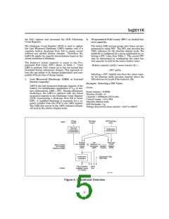
General Description
rectly indicated using a five-seg-
ment LED display. These segments
are used to graphically indicate
nominal available charge.
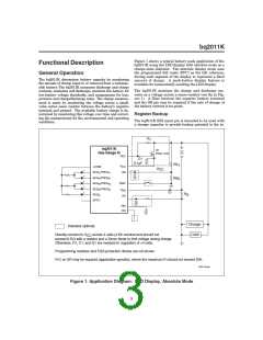
The bq2011K Gas Gauge IC is in-
tended for battery-pack installation to
maintain an accurate record of a bat-
tery’s available charge. The IC moni-
tors a voltage drop across a sense re-
sistor connected in series between the
negative battery terminal and ground
to determine charge and discharge ac-
tivity of the battery. The bq2011K is
designed for systems such as power
tools with very high discharge rates.
➤ Designed for portable equipment
such as power tools with high dis-
charge rates
The bq2011K supports a simple
single-line bidirectional serial link to
an external processor (common
ground). The bq2011K outputs bat-
tery information in response to exter-
nal commands over the serial link. To
support subassembly testing, the
outputs may also be controlled by
command. The external processor
may also overwrite some of the
bq2011K gas gauge data registers.
➤ Designed for battery pack inte-
gration
- 120µA typical standby current
(self-discharge estimation mode)
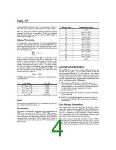
Battery self-discharge is estimated
based on an internal timer and tem-
perature sensor. Compensations for
battery temperature and rate of
charge or discharge are applied to
the charge, discharge, and
selfdischarge calculations to provide
available charge information across
a wide range of operating conditions.
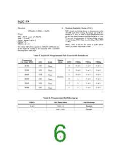
Initial battery capacity is set using
the PROG1-4 and SPFC pins. Actual
battery capacity is automatically
“learned” in the course of a dis-
charge cycle from full to empty and
may be displayed depending on the
display mode.
- Small size enables imple-
1
mentations in as little as
square inch of PCB
2
The bq2011K may operate directly
from four cells. With the REF out-
put and an external transistor, a
simple, inexpensive regulator can be
built to provide VCC from a greater
number of cells.
➤ Direct drive of LEDs for capacity
display
➤ Self-discharge compensation us-
ing internal temperature sensor
Internal registers include available
charge, temperature, capacity, battery
ID, and battery status.
➤ Simple single-wire serial commu-
nications port for subassembly
testing
➤ 16-pin narrow SOIC
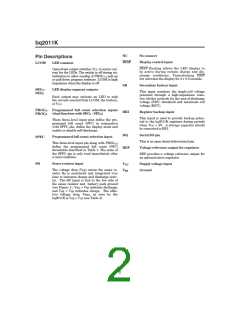
Pin Connections
Pin Names
LCOM
LED common output
REF
NC
Voltage reference output
No connect
SEG1/PROG1 LED segment 1/ Program
1 input
LCOM
1
2
3
4
5
6
16
15
14
13
12
11
V
CC
SEG /PROG
REF
NC
DQ
RBI
SB
1
1
2
3
4
5
DQ
Serial communications
input/output
SEG2/PROG2 LED segment 2 / Program
2 input
SEG /PROG
2
SEG /PROG
3
RBI
SB
Register backup input
Battery sense input
Display control input
Sense resistor input
3.0–6.5V
SEG3/PROG3 LED segment 3/ Program
3 input
SEG /PROG
4
SEG
SEG4/PROG4 LED segment 4/ Program
4 input
DISP
SR
SPFC
7
8
10
9
DISP
SR
V
SS
SEG5
SPFC
LED segment 5
VCC
VSS
16-Pin Narrow SOIC
Programmed full count
selection input
PN2011JK.eps
Negative battery terminal
10/97 B
1

 TI [ TEXAS INSTRUMENTS ]