AM6548, AM6528, AM6526
ZHCSLA7B –DECEMBER 2019 –REVISED JUNE 2021
www.ti.com.cn
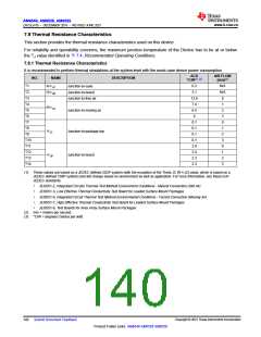
7.8 Thermal Resistance Characteristics
This section provides the thermal resistance characteristics used on this device.
For reliability and operability concerns, the maximum junction temperature of the Device has to be at or below
the TJ value identified in 节7.4, Recommended Operating Conditions.
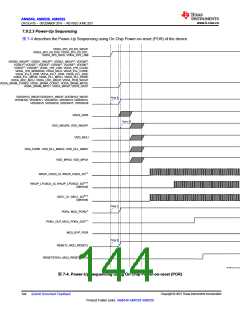
7.8.1 Thermal Resistance Characteristics
It is recommended to perform thermal simulations at the system level with the worst case device power consumption
ACD
AIR FLOW
(m/s)(2)
NO.
NAME
RΘJC
DESCRIPTION
°C/W(1) (3)
T1
0.2
3.1
12.8
7.4
6.5
6
N/A
N/A
0
Junction-to-case
Junction-to-board
Junction-to-free air
T2
RΘJB
T3
T4
1
RΘJA
T5
Junction-to-moving air
2
T6
3
T7
0.1
0.1
0.1
0.1
2.9
2.4
2.3
2.3
0
T8
1
Junction-to-package top
ΨJT
T9
2
T10
T11
T12
T13
T14
3
0
1
Junction-to-board
ΨJB
2
3
(1) These values are based on a JEDEC defined 2S2P system (with the exception of the Theta JC [RΘJC] value, which is based on a
JEDEC defined 1S0P system) and will change based on environment as well as application. For more information, see these EIA/
JEDEC standards:
•
•
•
•
•
JESD51-2, Integrated Circuits Thermal Test Method Environment Conditions - Natural Convection (Still Air)
JESD51-3, Low Effective Thermal Conductivity Test Board for Leaded Surface Mount Packages
JESD51-6, Integrated Circuit Thermal Test Method Environmental Conditions - Forced Convection (Moving Air)
JESD51-7, High Effective Thermal Conductivity Test Board for Leaded Surface Mount Packages
JESD51-9, Test Boards for Area Array Surface Mount Packages
(2) m/s = meters per second.
(3) °C/W = degrees Celsius per watt.
Copyright © 2021 Texas Instruments Incorporated
140 Submit Document Feedback
Product Folder Links: AM6548 AM6528 AM6526

 TI [ TEXAS INSTRUMENTS ]