AM3359, AM3358, AM3357
AM3356, AM3354, AM3352
SPRS717F –OCTOBER 2011–REVISED APRIL 2013
www.ti.com
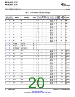
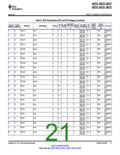
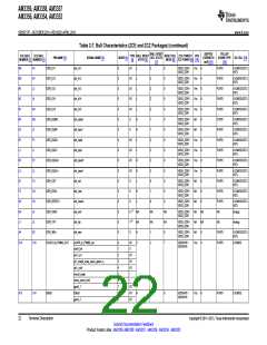
2.2 Ball Characteristics
The AM335x ARM Cortex-A8 Microprocessors (MPUs) Technical Reference Manual (literature number
SPRUH73) and this document may reference internal signal names when discussing peripheral input and
output signals since many of the AM335x package terminals can be multiplexed to one of several
peripheral signals. The following table has a Pin Name column that lists all device terminal names and a
Signal Name column that lists all internal signal names multiplexed to each terminal which provides a
cross reference of internal signal names to terminal names. This table also identifies other important
terminal characteristics.
1. BALL NUMBER: Package ball numbers associated with each signals.
2. PIN NAME: The name of the package pin or terminal.
Note: The table does not take into account subsystem terminal multiplexing options.
3. SIGNAL NAME: The signal name for that pin in the mode being used.
4. MODE: Multiplexing mode number.
(a) Mode 0 is the primary mode; this means that when mode 0 is set, the function mapped on the
terminal corresponds to the name of the terminal. There is always a function mapped on the
primary mode. Notice that primary mode is not necessarily the default mode.
Note: The default mode is the mode at the release of the reset; also see the RESET REL. MODE
column.
(b) Modes 1 to 7 are possible modes for alternate functions. On each terminal, some modes are
effectively used for alternate functions, while some modes are not used and do not correspond to a
functional configuration.
5. TYPE: Signal direction
–
–
–
–
–
–
–
–
I = Input
O = Output
IO = Input and Output
D = Open drain
DS = Differential
A = Analog
PWR = Power
GND = Ground
Note: In the safe_mode, the buffer is configured in high-impedance.
6. BALL RESET STATE: State of the terminal while the active low PWRONRSTn terminal is low.
–
0: The buffer drives VOL (pulldown or pullup resistor not activated)
0(PD): The buffer drives VOL with an active pulldown resistor
1: The buffer drives VOH (pulldown or pullup resistor not activated)
1(PU): The buffer drives VOH with an active pullup resistor
Z: High-impedance
–
–
–
–
L: High-impedance with an active pulldown resistor
H : High-impedance with an active pullup resistor
7. BALL RESET REL. STATE: State of the terminal after the active low PWRONRSTn terminal
transitions from low to high.
–
0: The buffer drives VOL (pulldown or pullup resistor not activated)
0(PD): The buffer drives VOL with an active pulldown resistor
1: The buffer drives VOH (pulldown or pullup resistor not activated)
1(PU): The buffer drives VOH with an active pullup resistor
Z: High-impedance.
–
–
–
–
L: High-impedance with an active pulldown resistor
H : High-impedance with an active pullup resistor
8. RESET REL. MODE: The mode is automatically configured after the active low PWRONRSTn terminal
transitions from low to high.
18
Terminal Description
Copyright © 2011–2013, Texas Instruments Incorporated
Submit Documentation Feedback
Product Folder Links: AM3359 AM3358 AM3357 AM3356 AM3354 AM3352

 TI [ TEXAS INSTRUMENTS ]