ADS1291
ADS1292
ADS1292R
SBAS502A –DECEMBER 2011–REVISED MARCH 2012
www.ti.com
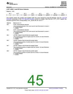
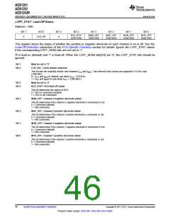
LOFF_STAT: Lead-Off Status
Address = 08h
BIT 7
0
BIT 6
BIT 5
0
BIT 4
BIT 3
BIT 2
BIT 1
BIT 0
RLD_STAT
(read only)
IN2N_OFF
(read only)
IN2P_OFF
(read only)
IN1N_OFF
(read only)
IN1P_OFF
(read only)
CLK_DIV
This register stores the status of whether the positive or negative electrode on each channel is on or off. See the
Lead-Off Detection subsection of the ECG-Specific Functions section for details. Ignore the LOFF_STAT values
if the corresponding LOFF_SENS bits are not set to '1'.
'0' is lead-on (default) and '1' is lead-off. When the LOFF_SENS bits[3:0] are '0', the LOFF_STAT bits should be
ignored.
Bit 7
Bit 6
Must be set to '0'
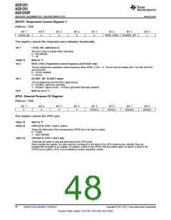
CLK_DIV : Clock divider selection
This bit sets the modultar divider ratio between fCLK and fMOD. Two external clock values are supported: 512 kHz and
2.048 MHz.
0 = fCLK and fMOD/4 (default, use when fCLK = 512 kHz)
1 = fCLK and fMOD/16 (use when fCLK = 2.048 MHz)
Bit 5
Bit 4
Must be set to '0'
RLD_STAT: RLD lead-off status
This bit determines the status of RLD.
0 = RLD is connected (default)
1 = RLD is not connected
Bit 3
Bit 2
Bit 1
Bit 0
IN2N_OFF: Channel 2 negative electrode status
This bit determines if the channel 2 negative electrode is connected or not.
0 = Connected (default)
1 = Not connected
IN2P_OFF: Channel 2 positive electrode status
This bit determines if the channel 2 positive electrode is connected or not.
0 = Connected (default)
1 = Not connected
IN1N_OFF: Channel 1 negative electrode status
This bit determines if the channel 1 negative electrode is connected or not.
0 = Connected (default)
1 = Not connected
IN1P_OFF: Channel 1 positive electrode status
This bit determines if the channel 1 positive electrode is connected or not.
0 = Connected (default)
1 = Not connected
46
Submit Documentation Feedback
Copyright © 2011–2012, Texas Instruments Incorporated
Product Folder Link(s): ADS1291 ADS1292 ADS1292R

 TI [ TEXAS INSTRUMENTS ]