ADS1291
ADS1292
ADS1292R
SBAS502A –DECEMBER 2011–REVISED MARCH 2012
www.ti.com
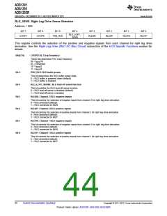
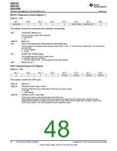
RLD_SENS: Right Leg Drive Sense Selection
Address = 06h
BIT 7
BIT 6
BIT 5
BIT 4
BIT 3
BIT 2
BIT 1
BIT 0
RLD_LOFF_
SENS
CHOP1
CHOP0
PDB_RLD
RLD2N
RLD2P
RLD1N
RLD1P
This register controls the selection of the positive and negative signals from each channel for right leg drive
derivation. See the Right Leg Drive (RLD DC Bias Circuit) subsection of the ECG-Specific Functions section for
details.
Bits[7:6]
CHOP[1:0]: Chop frequency
These bits determine PGA chop frequency
00 = fMOD/16
01 = Reserved
10 = fMOD/2
11 = fMOD/4
Bit 5
Bit 4
Bit 3
Bit 2
Bit 1
Bit 0
PDB_RLD: RLD buffer power
This bit determines the RLD buffer power state.
0 = RLD buffer is powered down (default)
1 = RLD buffer is enabled
RLD_LOFF_SENSE: RLD lead-off sense function
This bit enables the RLD lead-off sense function.
0 = RLD lead-off sense is disabled (default)
1 = RLD lead-off sense is enabled
RLD2N: Channel 2 RLD negative inputs
This bit controls the selection of negative inputs from channel 2 for right leg drive derivation.
0 = Not connected (default)
1 = RLD connected to IN2N
RLD2P: Channel 2 RLD positive inputs
This bit controls the selection of positive inputs from channel 2 for right leg drive derivation.
0 = Not connected (default)
1 = RLD connected to IN2P
RLD1N: Channel 1 RLD negative inputs
This bit controls the selection of negative inputs from channel 1 for right leg drive derivation.
0 = Not connected (default)
1 = RLD connected to IN1N
RLD1P: Channel 1 RLD positive inputs
This bit controls the selection of positive inputs from channel 1 for right leg drive derivation.
0 = Not connected (default)
1 = RLD connected to IN1P
44
Submit Documentation Feedback
Copyright © 2011–2012, Texas Instruments Incorporated
Product Folder Link(s): ADS1291 ADS1292 ADS1292R

 TI [ TEXAS INSTRUMENTS ]