ADS1291
ADS1292
ADS1292R
SBAS502A –DECEMBER 2011–REVISED MARCH 2012
www.ti.com
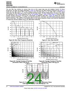
ANALOG INPUT
The ADS1291, ADS1292, and ADS1292R analog input is fully differential. Assuming PGA = 1, the differential
input (INP – INN) can span between –VREF to +VREF. Note that the absolute range for INP and INN must be
between AVSS – 0.3 V and AVDD + 0.3 V. Refer to Table 10 for an explanation of the correlation between the
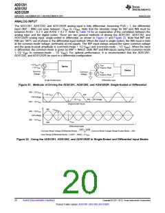
analog input and the digital codes. There are two general methods of driving the ADS1291, ADS1292, and
ADS1292R analog input: single-ended or differential, as shown in Figure 21 and Figure 22. Note that INP and
INN are 180°C out-of-phase in the differential input method. When the input is single-ended, the INN input is held
at the common-mode voltage, preferably at mid-supply. The INP input swings around the same common voltage
and the peak-to-peak amplitude is (common-mode + 1/2 VREF) and (common-mode – 1/2 VREF). When the input
is differential, the common-mode is given by (INP + INN)/2. Both INP and INN inputs swing from (common-mode
+ 1/2 VREF to common-mode – 1/2 VREF). For optimal performance, it is recommended that the ADS1291,
ADS1292, and ADS1292R be used in a differential configuration.
-1/2 VREF to
VREF
Device
+1/2 VREF
Peak-to-Peak
Device
Common
Voltage
Common
Voltage
VREF
Peak-to-Peak
Single-Ended Input
Differential Input
Figure 21. Methods of Driving the ADS1291, ADS1292, and ADS1292R: Single-Ended or Differential
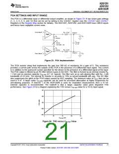
CM + 1/2 VREF
+1/2 VREF
INP
CM Voltage
-1/2 VREF
INN = CM Voltage
CM - 1/2 VREF
t
Single-Ended Inputs
INP
INN
+VREF
CM + 1/2 VREF
CM Voltage
CM - 1/2 VREF
-VREF
t
Differential Inputs
(INP) + (INN)
, Common-Mode Voltage (Single-Ended Mode) = INN.
Common-Mode Voltage (Differential Mode) =
2
Input Range (Differential Mode) = (AINP - AINN) = 2 VREF
.
Figure 22. Using the ADS1291, ADS1292, and ADS1292R in Single-Ended and Differential Input Modes
20
Submit Documentation Feedback
Copyright © 2011–2012, Texas Instruments Incorporated
Product Folder Link(s): ADS1291 ADS1292 ADS1292R

 TI [ TEXAS INSTRUMENTS ]