ADS1291
ADS1292
ADS1292R
www.ti.com
SBAS502A –DECEMBER 2011–REVISED MARCH 2012
Auxiliary Differential Input (RESP_MODN/IN3N, RESP_MODN/IN3P)
In applications where the respiration modulator output is not used, the RESP_MODN/IN3N and
RESP_MODN/IN3P signals can be used as a third multiplexed differential input channel. These inputs can be
multiplexed to either of the ADC channels.
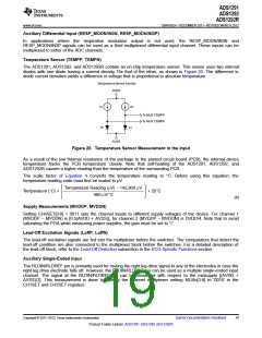
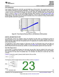
Temperature Sensor (TEMPP, TEMPN)
The ADS1291, ADS1292, and ADS1292R contain an on-chip temperature sensor. This sensor uses two internal
diodes with one diode having a current density 16x that of the other, as shown in Figure 20. The difference in
diode current densities yields a difference in voltage that is proportional to absolute temperature.
Temperature Sensor Monitor
AVDD
1x
2x
To MUX TEMPP
To MUX TEMPN
8x
1x
AVSS
Figure 20. Temperature Sensor Measurement in the Input
As a result of the low thermal resistance of the package to the printed circuit board (PCB), the internal device
temperature tracks the PCB temperature closely. Note that self-heating of the ADS1291, ADS1292, and
ADS1292R causes a higher reading than the temperature of the surrounding PCB.
The scale factor of Equation 4 converts the temperature reading to °C. Before using this equation, the
temperature reading code must first be scaled to μV.
Temperature Reading (mV) - 145,300 mV
Temperature (°C) =
+ 25°C
490 mV/°C
(4)
Supply Measurements (MVDDP, MVDDN)
Setting CHnSET[3:0] = 0011 sets the channel inputs to different supply voltages of the device. For channel 1
(MVDDP – MVDDN) is [0.5(AVDD + AVSS)]; for channel 2 (MVDDP – MVDDN) is DVDD/4. Note that to avoid
saturating the PGA while measuring power supplies, the gain must be set to '1'.
Lead-Off Excitation Signals (LoffP, LoffN)
The lead-off excitation signals are fed into the multiplexer before the switches. The comparators that detect the
lead-off condition are also connected to the multiplexer block before the switches. For a detailed description of
the lead-off block, refer to the Lead-Off Detection subsection in the ECG-Specific Functions section.
Auxiliary Single-Ended Input
The RLDIN/RLDREF pin is primarily used for routing the right leg drive signal to any of the electrodes in case the
right leg drive electrode falls off. However, the RLDIN/RLDREF pin can be used as a multiple single-ended input
channel. The signal at the RLDIN/RLDREF pin can be measured with respect to the midsupply [(AVDD +
AVSS)/2]. This measurement is done by setting the channel multiplexer setting MUXn[3:0] to '0010' in the
CH1SET and CH2SET registers.
Copyright © 2011–2012, Texas Instruments Incorporated
Submit Documentation Feedback
19
Product Folder Link(s): ADS1291 ADS1292 ADS1292R

 TI [ TEXAS INSTRUMENTS ]