ADS1299
SBAS499A –JULY 2012–REVISED AUGUST 2012
www.ti.com
BIAS LEAD-OFF
The ADS1299 provides two modes for determining whether the BIAS is correctly connected:
•
•
BIAS lead-off detection during normal operation
BIAS lead-off detection during power-up
The following sections provide details of the two modes of operation.
BIAS Lead-Off Detection During Normal Operation
During normal operation, the ADS1299 BIAS lead-off at power-up function cannot be used because it is
necessary to power off the BIAS amplifier.
BIAS Lead Off Detection At Power-Up
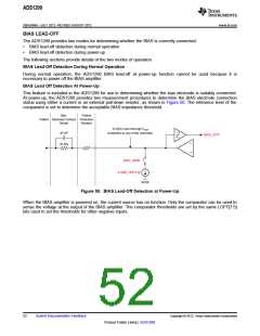
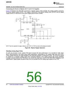
This feature is included in the ADS1299 for use in determining whether the bias electrode is suitably connected.
At power-up, the ADS1299 provides two measurement procedures to determine the BIAS electrode connection
status using either a current or an external pull-down resistor, as shown in Figure 50. The reference level of the
comparator is set to determine the acceptable BIAS impedance threshold.
Skin,
Patient
Patient Electrode Contact Protection
Model
47 nF
Resistor
To ADC input (through VREF
connection to any of the channels).
BIAS_STAT
51 kW
BIAS_SENS
ILGND_OFF[1:0]
AVSS
Figure 50. BIAS Lead-Off Detection at Power-Up
When the BIAS amplifier is powered on, the current source has no function. Only the comparator can be used to
sense the voltage at the output of the BIAS amplifier. The comparator thresholds are set by the same LOFF[7:5]
bits used to set the thresholds for other negative inputs.
52
Submit Documentation Feedback
Copyright © 2012, Texas Instruments Incorporated
Product Folder Link(s): ADS1299

 TI [ TEXAS INSTRUMENTS ]