ADS1299
www.ti.com
SBAS499A –JULY 2012–REVISED AUGUST 2012
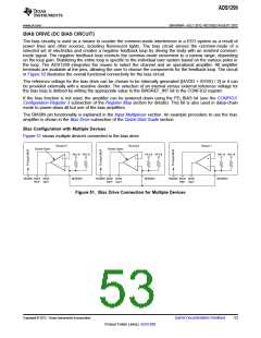
INPUT MULTIPLEXER (Measuring the BIAS Drive Signal)
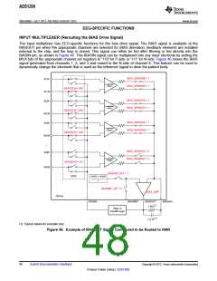
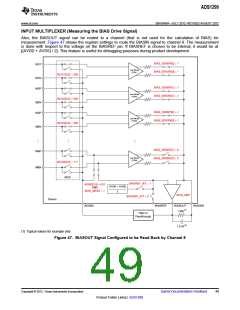
Also, the BIASOUT signal can be routed to a channel (that is not used for the calculation of BIAS) for
measurement. Figure 47 shows the register settings to route the BIASIN signal to channel 8. The measurement
is done with respect to the voltage on the BIASREF pin. If BIASREF is chosen to be internal, it would be at
[(AVDD + AVSS) / 2]. This feature is useful for debugging purposes during product development.
BIAS_SENSP[0] = 1
IN1P
Low-Noise
PGA1
BIAS_SENSN[0] = 1
MUX1[2:0] = 000
IN1N
BIAS_SENSP[1] = 1
IN2P
Low-Noise
PGA2
BIAS_SENSN[1] = 1
MUX2[2:0] = 000
IN2N
BIAS_SENSP[2] = 1
IN3P
Low-Noise
PGA3
BIAS_SENSN[2] = 1
MUX3[2:0] = 000
IN3N
BIAS_SENSP[7] = 0
IN8P
Low-Noise
PGA8
BIAS_SENSN[7] = 0
MUX8[2:0] = 111
IN8N
MUX
BIASREF_INT = 1
MUX8[2:0] = 010
(AVDD + AVSS)
AND
BIAS_MEAS = 1
2
BIAS_AMP
BIASREF_INT = 0
Device
BIASIN
BIASREF
BIASOUT
BIASINV
(1)
1 MW
Filter or
Feedthrough
1.5 nF(1)
(1) Typical values for example only.
Figure 47. BIASOUT Signal Configured to be Read Back by Channel 8
Copyright © 2012, Texas Instruments Incorporated
Submit Documentation Feedback
49
Product Folder Link(s): ADS1299

 TI [ TEXAS INSTRUMENTS ]