ADS1299
SBAS499A –JULY 2012–REVISED AUGUST 2012
www.ti.com
EEG-SPECIFIC FUNCTIONS
INPUT MULTIPLEXER (Rerouting the BIAS Drive Signal)
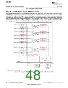
The input multiplexer has EEG-specific functions for the bias drive signal. The BIAS signal is available at the
BIASOUT pin when the appropriate channels are selected for BIAS derivation, feedback elements are installed
external to the chip, and the loop is closed. This signal can either be fed after filtering or fed directly into the
BIASIN pin, as shown in Figure 46. This BIASIN signal can be multiplexed into any input electrode by setting the
MUX bits of the appropriate channel set registers to '110' for P-side or '111' for N-side. Figure 46 shows the BIAS
signal generated from channels 1, 2, and 3 and routed to the N-side of channel 8. This feature can be used to
dynamically change the electrode that is used as the reference signal to drive the patient body.
BIAS_SENSP[0] = 1
IN1P
Low-Noise
PGA1
BIAS_SENSN[0] = 1
MUX1[2:0] = 000
IN1N
BIAS_SENSP[1] = 1
IN2P
Low-Noise
PGA2
BIAS_SENSN[1] = 1
MUX2[2:0] = 000
IN2N
BIAS_SENSP[2] = 1
IN3P
Low-Noise
PGA3
BIAS_SENSN[2] = 1
MUX3[2:0] = 000
IN3N
BIAS_SENSP[7] = 0
IN8P
Low-Noise
PGA8
BIAS_SENSN[7] = 0
MUX8[2:0] = 111
IN8N
BIASREF_INT = 1
MUX
(AVDD + AVSS)
2
BIASREF_INT = 0
BIAS_AMP
Device
BIASIN
BIASREF
BIASOUT
BIASINV
(1)
1 MW
Filter or
Feedthrough
1.5 nF(1)
(1) Typical values for example only.
Figure 46. Example of BIASOUT Signal Configured to be Routed to IN8N
48
Submit Documentation Feedback
Copyright © 2012, Texas Instruments Incorporated
Product Folder Link(s): ADS1299

 TI [ TEXAS INSTRUMENTS ]