ADS1299
www.ti.com
SBAS499A –JULY 2012–REVISED AUGUST 2012
DC Lead-Off
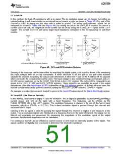
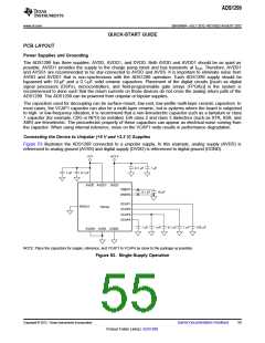
In this method, the lead-off excitation is with a dc signal. The dc excitation signal can be chosen from either an
external pull-up or pull-down resistor or an internal current source or sink, as shown in Figure 49. One side of the
channel is pulled to supply and the other side is pulled to ground. The pull-up and pull-down current can be
swapped (as shown in Figure 49b and Figure 49c) by setting the bits in the LOFF_FLIP register. In case of a
current source or sink, the magnitude of the current can be set by using the ILEAD_OFF[1:0] bits in the LOFF
register. The current source or sink gives larger input impedance compared to the 10-MΩ pull-up or pull-down
resistor.
AVDD
AVDD
AVDD
Device
Device
Device
10 MW
INP
INN
INP
INN
INP
INN
Low-Noise
PGAn
Low-Noise
PGAn
Low-Noise
PGAn
10 MW
AVSS
a) External Pull-Up or Pull-Down Resistors
b) Input Current Source
(LOFF_FLIP = 0)
c) Input Current Source
(LOFF_FLIP = 1)
Figure 49. DC Lead-Off Excitation Options
Sensing of the response can be done either by searching the digital output code from the device or by monitoring
the input voltages with an on-chip comparator. If either electrode is off, the pull-up and pull-down resistors
saturate the channel. Searching the output code determines if either the P-side or the N-side is off. To pinpoint
which one is off, the comparators must be used. The input voltage is also monitored using a comparator and a 3-
bit DAC whose levels are set by the COMP_TH[2:0] bits in the LOFF register. The output of the comparators are
stored in the LOFF_STATP and LOFF_STATN registers. These registers are available as a part of the output
data stream. (See the Data Output (DOUT) subsection of the SPI Interface section.) If dc lead-off is not used, the
lead-off comparators can be powered down by setting the PD_LOFF_COMP bit in the CONFIG4 register.
An example procedure to turn on dc lead-off is given in the Lead-Off subsection of the Quick-Start Guide section.
AC Lead-Off (One Time or Periodic)
In this method, an in-band ac signal is used for excitation. The ac signal is generated by alternatively providing a
current source and sink at the input with a fixed frequency. The frequency can be chosen by the
FLEAD_OFF[1:0] bits in the LOFF register. The excitation frequency is chosen to be one of the two in-band
frequency selections (7.8 Hz or 31.2 Hz). This in-band excitation signal is passed through the channel and
measured at the output.
Sensing of the ac signal is done by passing the signal through the channel to digitize it and measure at the
output. The ac excitation signals are introduced at a frequency that is in the band of interest. The signal can be
filtered out separately and processed. By measuring the magnitude of the excitation signal at the output
spectrum, the electrode impedance can be calculated.
For continuous lead-off, an out-of-band ac current source or sink must be externally applied to the inputs. This
signal can then be digitally post processed to determine the electrode impedance.
Copyright © 2012, Texas Instruments Incorporated
Submit Documentation Feedback
51
Product Folder Link(s): ADS1299

 TI [ TEXAS INSTRUMENTS ]