ADS1115-Q1
www.ti.com
SBAS563 –DECEMBER 2011
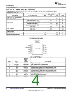
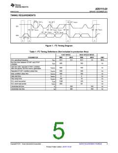
TIMING REQUIREMENTS
tLOW
tF
tR
tHDSTA
SCL
tSUSTO
tHDSTA
tHIGH tSUSTA
tHDDAT
tSUDAT
SDA
tBUF
P
S
S
P
Figure 1. I2C Timing Diagram
Table 1. I2C Timing Definitions (Not included in production flow)
FAST MODE
HIGH-SPEED MODE
PARAMETER
MIN
MAX
MIN
MAX
UNIT
SCL operating frequency
fSCL
tBUF
0.01
0.4
0.01
3.4
MHz
Bus free time between START and STOP
condition
600
160
160
ns
ns
Hold time after repeated START condition.
After this period, the first clock is generated.
tHDSTA
600
Repeated START condition setup time
Stop condition setup time
Data hold time
tSUSTA
tSUSTO
tHDDAT
tSUDAT
tLOW
tHIGH
tF
600
600
0
160
160
0
ns
ns
ns
ns
ns
ns
ns
ns
Data setup time
100
1300
600
10
SCL clock low period
SCL clock high period
Clock/data fall time
160
60
300
300
160
160
Clock/data rise time
tR
Copyright © 2011, Texas Instruments Incorporated
Submit Documentation Feedback
5
Product Folder Link(s) :ADS1115-Q1

 TI [ TEXAS INSTRUMENTS ]