ADS1115-Q1
SBAS563 –DECEMBER 2011
www.ti.com
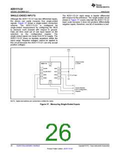
SINGLE-ENDED INPUTS
The ADS1115-Q1 input range is bipolar differential
with respect to the reference. The single-ended circuit
shown in Figure 37 covers only half the ADS1115-Q1
input scale because it does not produce differentially
negative inputs; therefore, one bit of resolution is lost.
Although the ADS1115-Q1 has two differential inputs,
the device can easily measure four single-ended
signals. Figure 37 shows a single-ended connection
scheme. The ADS1115-Q1 is configured for
single-ended measurement by configuring the MUX
to measure each channel with respect to ground.
Data are then read out of one input based on the
selection on the configuration register. The
single-ended signal can range from 0V to supply. The
ADS1115-Q1 loses no linearity anywhere within the
input range. Negative voltages cannot be applied to
this circuit because the ADS1115-Q1 can only accept
positive voltages.
VDD
Output Codes
0-32767
10
ADS1115
SCL
1
2
3
4
ADDR
SDA
VDD
AIN3
AIN2
9
8
7
6
ALERT/RDY
GND
0.1mF (typ)
AIN0
AIN1
5
Inputs Selected
from Configuration
Register
NOTE: Digital and address pin connections omitted for clarity.
Figure 37. Measuring Single-Ended Inputs
26
Submit Documentation Feedback
Copyright © 2011, Texas Instruments Incorporated
Product Folder Link(s) :ADS1115-Q1

 TI [ TEXAS INSTRUMENTS ]