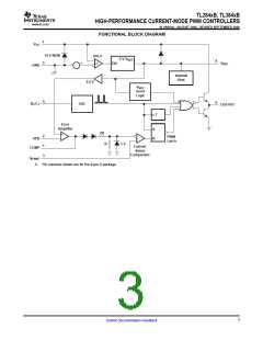
TL284xB, TL384xB
HIGH-PERFORMANCE CURRENT-MODE PWM CONTROLLERS
www.ti.com
SLVS610A–AUGUST 2006–REVISED SEPTEMBER 2006
Output Section Electrical Characteristics
VCC = 15 V(1), RT = 10 kΩ, CT = 3.3 nF, over recommended operating free-air temperature range (unless otherwise specified)
TL284xB
TYP(2)
13.5
13.5
0.1
TL384xB
TYP(2)
13.5
13.5
0.1
PARAMETER
High-level output voltage
Low-level output voltage
TEST CONDITIONS
IOH = –20 mA
UNIT
V
MIN
13
MAX
MIN
13
MAX
IOH = –200 mA
12
12
IOL = 20 mA
0.4
2.2
0.4
2.2
V
IOL = 200 mA
1.5
1.5
Rise time
CL = 1 nF, TJ = 25°C
CL = 1 nF, TJ = 25°C
VCC = 5 V, IOL = 1 mA
50
150
150
1.2
50
150
150
1.2
ns
ns
V
Fall time
50
50
UVLO saturation
0.7
0.7
(1) Adjust VCC above the start threshold before setting it to 15 V.
(2) All typical values are at TJ = 25°C.
Undervoltage-Lockout Section Electrical Characteristics
VCC = 15 V(1), RT = 10 kΩ, CT = 3.3 nF, over recommended operating free-air temperature range (unless otherwise specified)
TL284xB
TYP(2)
16
TL384xB
TYP(2)
16
PARAMETER
TEST CONDITIONS
TLx842B, TLx844B
UNIT
V
MIN
15
7.8
9
MAX
17
MIN
14.5
7.8
8.5
7
MAX
17.5
9
Start threshold voltage
TLx843B, TLx845B
TLx842B, TLx844B
TLx843B, TLx845B
8.4
9
8.4
10
11
10
11.5
8.2
Minimum operating voltage
after start-up
V
7
7.6
8.2
7.6
(1) Adjust VCC above the start threshold before setting it to 15 V.
(2) All typical values are at TJ = 25°C.
Pulse-Width Modulator Section Electrical Characteristics
VCC = 15 V(1), RT = 10 kΩ, CT = 3.3 nF, over recommended operating free-air temperature range (unless otherwise specified)
TL284xB
TYP(2)
96
TL384xB
TYP(2)
96
PARAMETER
TEST CONDITIONS
UNIT
MIN
94
MAX
100
50
MIN
94
MAX
100
50
TL3842B, TL3843B
TL3844B, TL3845B
Maximum duty cycle
Minimum duty cycle
%
%
47
48
47
48
0
0
(1) Adjust VCC above the start threshold before setting it to 15 V.
(2) All typical values are at TJ = 25°C.
Supply Voltage Electrical Characteristics
VCC = 15 V(1), RT = 10 kΩ, CT = 3.3 nF, over recommended operating free-air temperature range (unless otherwise specified)
TL284xB
TYP(2)
0.3
TL384xB
TYP(2)
0.3
PARAMETER
Start-up current
TEST CONDITIONS
UNIT
MIN
MAX
0.5
MIN
MAX
0.5
mA
mA
V
Operating supply current
Limiting voltage
VFB and ISENSE at 0 V
ICC = 25 mA
11
17
11
17
30
34
30
34
(1) Adjust VCC above the start threshold before setting it to 15 V.
(2) All typical values are at TJ = 25°C.
7
Submit Documentation Feedback

 TI [ TEXAS INSTRUMENTS ]