TL284xB, TL384xB
HIGH-PERFORMANCE CURRENT-MODE PWM CONTROLLERS
www.ti.com
SLVS610A–AUGUST 2006–REVISED SEPTEMBER 2006
APPLICATION INFORMATION
The error-amplifier configuation circuit is shown in Figure 1.
2.5 V
0.5 mA
Error
Amplifier
+
−
VFB
Z
i
COMP
Z
f
A. Error amplifier can source or sink up to 0.5 mA.
Figure 1. Error-Amplifier Configuration
The current-sense circuit is shown in Figure 2.
Error
I
S
Amplifier
(see Note A)
2R
+
−
R
1 V
Current-Sense
Comparator
COMP
R
f
I
SENSE
R
S
C
f
GND
A. Peak current (IS) is determined by the formula: IS(max) = 1 V/RS
B. A small RC filter formed by resistor Rf and capacitor Cf may be required to suppress switch transients.
Figure 2. Current-Sense Circuit
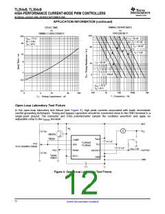
The oscillator frequency is set using the circuit shown in Figure 3. The frequency is calculated as:
f = 1 / RTCT
For RT > 5 kΩ:
f ≈ 1.72 / RTCT
V
REF
R
T
R /C
T
T
C
T
GND
Figure 3. Oscillator Section
11
Submit Documentation Feedback

 TI [ TEXAS INSTRUMENTS ]