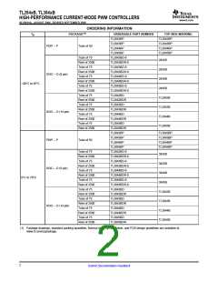
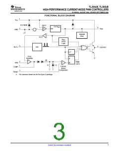
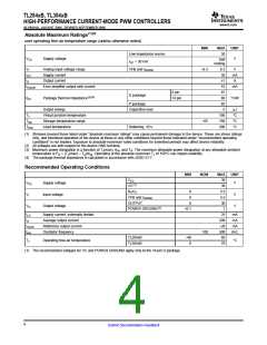
TL284xB, TL384xB
HIGH-PERFORMANCE CURRENT-MODE PWM CONTROLLERS
www.ti.com
SLVS610A–AUGUST 2006–REVISED SEPTEMBER 2006
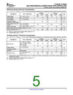
Error-Amplifier Section Electrical Characteristics
VCC = 15 V(1), RT = 10 kΩ, CT = 3.3 nF, over recommended operating free-air temperature range (unless otherwise specified)
TL284xB
TYP(2)
2.5
TL384xB
TYP(2)
2.5
PARAMETER
TEST CONDITIONS
COMP = 2.5 V
UNIT
MIN
MAX
2.55
–1
MIN
MAX
2.58
–2
Feedback input voltage
Input bias current
2.45
2.42
V
–0.3
–0.3
µA
Open-loop voltage
amplification
VO = 2 V to 4 V
65
90
65
90
dB
Gain-bandwidth product
0.7
60
1
70
0.7
60
1
70
MHz
dB
Supply-voltage rejection ratio VCC = 12 V to 25 V
Output sink current
VFB = 2.7 V, COMP = 1.1 V
2
6
2
6
mA
mA
Output source current
VFB = 2.3 V, COMP = 5 V
–0.5
–0.8
–0.5
–0.8
VFB = 2.3 V,
RL = 15 kΩ to GND
High-level output voltage
Low-level output voltage
5
6
5
6
V
V
VFB = 2.7 V,
RL = 15 kΩ to GND
0.7
1.1
0.7
1.1
(1) Adjust VCC above the start threshold before setting it to 15 V.
(2) All typical values are at TJ = 25°C.
Current-Sense Section Electrical Characteristics
VCC = 15 V(1), RT = 10 kΩ, CT = 3.3 nF, over recommended operating free-air temperature range (unless otherwise specified)
TL284xB
TYP(2)
3
TL384xB
TYP(2)
3
PARAMETER
TEST CONDITIONS
UNIT
MIN
MAX
MIN
MAX
Voltage amplification(3)(4)
2.85
3.15
2.85
3.15
V/V
V
Current-sense comparator
threshold(3)
COMP = 5 V
0.9
1
1.1
0.9
1
1.1
Supply-voltage rejection
ratio(3)
VCC = 12 V to 25 V
70
70
dB
Input bias current
–2
–10
300
–2
–10
300
µA
Delay time to output
VFB = 0 V to 2 V
150
150
ns
(1) Adjust VCC above the start threshold before setting it to 15 V.
(2) All typical values are at TJ = 25°C.
(3) Measured at the trip point of the latch, with VFB at 0 V.
(4) Measured between ISENSE and COMP, with the input changing from 0 V to 0.8 V.
6
Submit Documentation Feedback

 TI [ TEXAS INSTRUMENTS ]