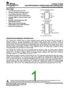
TL284xB, TL384xB
HIGH-PERFORMANCE CURRENT-MODE PWM CONTROLLERS
www.ti.com
SLVS610A–AUGUST 2006–REVISED SEPTEMBER 2006
Reference Section Electrical Characteristics
VCC = 15 V(1), RT = 10 kΩ, CT = 3.3 nF, over recommended operating free-air temperature range (unless otherwise specified)
TL284xB
TYP(2)
TL384xB
TYP(2)
PARAMETER
Output voltage
TEST CONDITIONS
IO = 1 mA, TJ = 25°C
UNIT
MIN
MAX
5.05
20
MIN
MAX
5.1
20
4.95
5
6
6
4.9
5
6
6
V
Line regulation
Load regulation
VCC = 12 V to 25 V
IO = 1 mA to 20 mA
mV
mV
25
25
Average temperature
coefficient of output voltage
0.2
0.4
5.1
0.2
0.4 mV/°C
Output voltage, worst-case
variation
VCC = 12 V to 25 V,
IO = 1 mA to 20 mA
4.9
4.82
–30
5.18
V
Output noise voltage
f = 10 Hz to 10 kHz, TJ = 25°C
50
5
50
5
µV
mV
mA
Output-voltage long-term drift After 1000 h at TJ = 25°C
25
25
Short-circuit output current
–30
–100
–180
–100
–180
(1) Adjust VCC above the start threshold before setting it to 15 V.
(2) All typical values are at TJ = 25°C.
Oscillator Section(1) Electrical Characteristics
VCC = 15 V(2), RT = 10 kΩ, CT = 3.3 nF, over recommended operating free-air temperature range (unless otherwise specified)
TL284xB
TYP(3)
TL384xB
TYP(3)
PARAMETER
TEST CONDITIONS
UNIT
MIN
49
MAX
MIN
49
MAX
TJ = 25°C, RT = 62 kΩ,
CT = 1 nF, Min = 225 kHz,
Max = 275 kHz
52
55
52
55
Initial accuracy
kHz
TJ = Full range
48
56
1
48
56
1
Voltage stability
Temperature stability
Amplitude
VCC = 12 V to 25 V
0.2
5
0.2
5
%
%
V
Peak to peak
1.7
8.3
1.7
8.3
TJ = 25°C, RT/CT = 2 V
RT/CT = 2 V
7.8
7.5
8.8
8.8
7.8
7.6
8.8
8.8
Discharge current
mA
(1) Output frequency equals oscillator frequency for the TL3842B and TL3843B. Output frequency is one-half the oscillator frequency for the
TL3844B and TL3845B.
(2) Adjust VCC above the start threshold before setting it to 15 V.
(3) All typical values are at TJ = 25°C.
5
Submit Documentation Feedback

 TI [ TEXAS INSTRUMENTS ]