71M6521BE
Energy Meter IC
DATA SHEET
JANUARY 2008
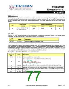
TMUX[4:0]
20AA[4:0]
2
R/W Selects one of 32 signals for TMUXOUT.
--
[4:0]
Selected Signal
DGND (analog)
Reserved
Reserved
VBIAS (analog)
Reserved
[4:0]
Selected Signal
Reserved
Reserved
Reserved
Not used
0x00
0x02
0x04
0x06
0x08
0x0A
0x01
0x03
0x05
0x07
0x09
0x0B
-0x13
0x15
Reserved
Reserved
Reserved
0x14
RTM (Real time
output from CE)
WDTR_E, comparator 1
Output AND V1LT3)
RXD, from optical in-
terface, after optional
inversion
0x16 – Not used
0x17
0x18
0x19
0x1B
0x1D
0x1F
MUX_SYNC
CK_MPU
Reserved
XFER_BUSY
0x1A
0x1C
0x1E
CK_10M
Reserved
CE_BUSY
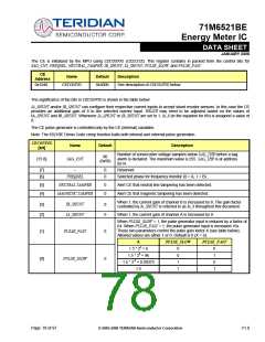
VERSION[7:0]
VREF_CAL
2006
--
0
--
0
R
The version index. This word may be read by firmware to determine
the silicon version.
VERSION[7:0]
Silicon Version
0000 0110
A06
2004[7]
R/W Brings VREF to VREF pad. This feature is disabled when
VREF_DIS=1.
VREF_DIS
WAKE_ARM
2004[3]
20A9[7]
0
0
1
--
R/W Disables the internal voltage reference.
W
Arm the autowake timer. Writing a 1 to this bit arms the autowake
timer and presets it with the values presently in WAKE_PRD and
WAKE_RES. The autowake timer is reset and disarmed whenever
the processor is in MISSION mode or BROWNOUT mode. The
timer must be armed at least three crystal clock cycles before the
SLEEP or LCD-ONLY mode is commanded.
WAKE_PRD
20A9[2:0]
001
--
R/W Sleep time. Time=WAKE_PRD[2:0]*WAKE_RES. Default=001.
Maximum value is 7.
WAKE_RES
WD_RST
20A9[3]
SFRE8[7]
0
0
--
0
R/W Resolution of WAKE timer: 1 – 1 minute, 0 – 2.5 seconds.
W
WD timer bit: Possible operations to this bit are:
Read: Gets the status of the flag IE_PLLFALL
Write 0: Clears the flag
Write 1:.Resets the WDT
WD_OVF
2002[2]
0
0
R/W The WD overflow status bit. This bit is set when the WD timer
overflows. It is powered by the nonvolatile supply and at bootup will
indicate if the part is recovering from a WD overflow or a power fault.
This bit should be cleared by the MPU on bootup. It is also
automatically cleared when RESET is high.
V1.0
© 2005-2008 TERIDIAN Semiconductor Corporation
Page: 75 of 97

 TERIDIAN [ TERIDIAN SEMICONDUCTOR CORPORATION ]