71M6521BE
Energy Meter IC
DATA SHEET
JANUARY 2008
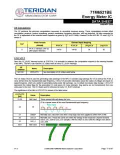
The CE is initialized by the MPU using CECONFIG (CESTATE). This register contains in packed form the control bits for
SAG_CNT, FREQSEL, NEUTRAL_TAMPER, IB_SHUNT, IA_SHUNT, PULSE_SLOW, and PULSE_FAST.
CE
Address
Name
Default
Description
0x1040
CECONFIG
0x5000
See description of CECONFIG below
The significance of the bits in CECONFIG is shown in the table below:
IA_SHUNT and/or IB_SHUNT can configure their respective current inputs to accept shunt resistor sensors. In this case the CE
provides an additional gain of 8 to the selected current input. WRATE may need to be adjusted based on the values of
IA_SHUNT and IB_SHUNT. Whenever IA_SHUNT or IB_SHUNT are set to 1, In_8 (in the equation for Kh) is assigned a value of
8.
The CE pulse generator is controlled only by the CE (internal) variables.
Note: The 6521BE Demo Code creep function halts both internal and external pulse generation.
CECONFIG
Name
Default
Description
[bit]
Number of consecutive voltage samples below SAG_THR before a sag
alarm is declared. The maximum value is 255. SAG_THR is at address
0x14.
80
(0x50)
[15:8]
SAG_CNT
[7]
[6]
--
0
0
Reserved
FREQSEL
Selected phase for frequency monitor (0 = A, 1 = B).
[5]
[4]
NEUTRAL TAMPER
MAGNETIC TAMPER
0
0
Alert CE that neutral line tampering has been detected.
Alert CE that magnetic tampering has been detected.
When 1, the current gain of channel B is increased by 8. The gain factor
controlled by In_SHUNT is referred to as In_8 throughout this document.
[3]
[2]
IB_SHUNT
IA_SHUNT
0
0
When 1, the current gain of channel A is increased by 8.
When PULSE_SLOW = 1, the pulse generator input is reduced by a factor of
64. When PULSE_FAST = 1, the pulse generator input is increased 16x.
These two parameters control the pulse gain factor X (see table below).
Allowed values are either 1 or 0. Default is 0 (X = 6).
[1]
[0]
PULSE_FAST
PULSE_SLOW
0
0
PULSE_SLOW
PULSE_FAST
X
1.5 * 22 = 6
1.5 * 26 = 96
1.5 * 2-4 = 0.09375
1.5
0
0
1
1
0
1
0
1
Page: 78 of 97
© 2005-2008 TERIDIAN Semiconductor Corporation
V1.0

 TERIDIAN [ TERIDIAN SEMICONDUCTOR CORPORATION ]