Document Number: PS-MPU-6500A-01
Revision: 1.1
Release Date: 03/05/2014
MPU-6500 Product Specification
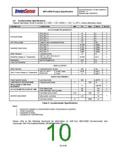
3.2 Accelerometer Specifications
Typical Operating Circuit of section 4.2, VDD = 1.8V, VDDIO = 1.8V, TA=25°C, unless otherwise noted.
PARAMETER
CONDITIONS
ACCELEROMETER SENSITIVITY
MIN
TYP
MAX
UNITS
NOTES
AFS_SEL=0
±2
±4
g
3
3
3
3
3
3
3
3
3
2
AFS_SEL=1
g
Full-Scale Range
AFS_SEL=2
±8
g
AFS_SEL=3
±16
g
ADC Word Length
Sensitivity Scale Factor
Output in two’s complement format
AFS_SEL=0
16
bits
LSB/g
LSB/g
LSB/g
LSB/g
%
16,384
8,192
4,096
2,048
±3
AFS_SEL=1
AFS_SEL=2
AFS_SEL=3
Initial Tolerance
Component-level
-40°C to +85°C AFS_SEL=0
Component-level
Sensitivity Change vs. Temperature
±0.026
%/°C
1
Nonlinearity
Best Fit Straight Line
±0.5
±2
%
%
1
1
Cross-Axis Sensitivity
ZERO-G OUTPUT
Initial Tolerance
Component-level, all axes
±60
±0.64
±1
mg
2
1
1
-40°C to +85°C,
Board-level
X and Y axes
Z axis
mg/°C
mg/°C
Zero-G Level Change vs. Temperature
NOISE PERFORMANCE
µg/√Hz
Power Spectral Density
Low noise mode
300
4
4
3
LOW PASS FILTER RESPONSE
Programmable Range
5
260
Hz
INTELLIGENCE FUNCTION
INCREMENT
mg/LSB
3
From Sleep mode
From Cold Start, 1ms VDD ramp
20
30
ms
ms
1
1
ACCELEROMETER STARTUP TIME
Low power (duty-cycled)
Duty-cycled, over temp
Low noise (active)
0.24
4
500
Hz
%
1
OUTPUT DATA RATE
±15
4000
Hz
Table 2: Accelerometer Specifications
Notes:
1. Derived from validation or characterization of parts, not guaranteed in production.
2. Tested in production.
3. Guaranteed by design.
4. Calculated from Total RMS Noise.
Please refer to the following document for information on Self-Test: MPU-6500 Accelerometer and
Gyroscope Self-Test Implementation; AN-MPU-6500A-02
10 of 40

 TDK [ TDK ELECTRONICS ]