ICM-20690
Communications
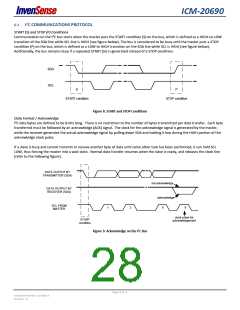
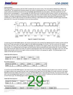
After beginning communications with the START condition (S), the master sends a 7-bit slave address followed by an 8th bit, the
read/write bit. The read/write bit indicates whether the master is receiving data from or is writing to the slave device. Then, the
master releases the SDA line and waits for the acknowledge signal (ACK) from the slave device. Each byte transferred must be
followed by an acknowledge bit. To acknowledge, the slave device pulls the SDA line LOW and keeps it LOW for the high period of
the SCL line. Data transmission is always terminated by the master with a STOP condition (P), thus freeing the communications line.
However, the master can generate a repeated START condition (Sr), and address another slave without first generating a STOP
condition (P). A LOW to HIGH transition on the SDA line while SCL is HIGH defines the stop condition. All SDA changes should take
place when SCL is low, with the exception of start and stop conditions.
SDA
SCL
1 – 7
8
9
1 – 7
8
9
1 – 7
8
9
S
P
START
STOP
ADDRESS
R/W
ACK
DATA
ACK
DATA
ACK
condition
condition
Figure 10. Complete I2C Data Transfer
To write the internal ICM-20690 registers, the master transmits the start condition (S), followed by the I2C address and the write bit
(0). At the 9th clock cycle (when the clock is high), the ICM-20690 acknowledges the transfer. Then the master puts the register
address (RA) on the bus. After the ICM-20690 acknowledges the reception of the register address, the master puts the register data
onto the bus. This is followed by the ACK signal, and data transfer may be concluded by the stop condition (P). To write multiple
bytes after the last ACK signal, the master can continue outputting data rather than transmitting a stop signal. In this case, the ICM-
20690 automatically increments the register address and loads the data to the appropriate register. The following figures show
single and two-byte write sequences.
Single-Byte Write Sequence
Master
Slave
S
AD+W
RA
DATA
DATA
P
ACK
ACK
ACK
ACK
ACK
Burst Write Sequence
Master
Slave
S
AD+W
RA
DATA
P
ACK
ACK
To read the internal ICM-20690 registers, the master sends a start condition, followed by the I2C address and a write bit, and then
the register address that is going to be read. Upon receiving the ACK signal from the ICM-20690, the master transmits a start signal
followed by the slave address and read bit. As a result, the ICM-20690 sends an ACK signal and the data. The communication ends
with a not acknowledge (NACK) signal and a stop bit from master. The NACK condition is defined such that the SDA line remains high
at the 9th clock cycle. The following figures show single and two-byte read sequences.
Single-Byte Read Sequence
Master
Slave
S
AD+W
RA
RA
S
AD+R
AD+R
NACK
P
ACK
ACK
ACK
DATA
Burst Read Sequence
Master AD+W
S
S
ACK
NACK
P
Page 29 of 76
Document Number: DS-000178
Revision: 1.0

 TDK [ TDK ELECTRONICS ]