Technical
Specification
IQ18xxxSKxxx
Mech2 Title
]
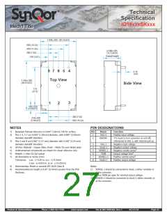
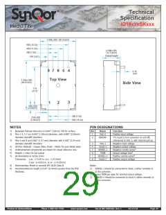
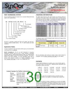
TOP VIEW
1.12
[ 28,3
1.436
[ 36,47 ]
]
.94
[ 23,9
]
.21
[ 5,3
1
]
3
2
1
.218 .020 [ 5,54 0,5
.350 .020 [ 8,89 0,5
]
]
.13 [ 3,2
]
.300 [ 7,62
]
BOTTOMSIDE
CLEARANCE
.010 [ 0,25
.14 [ 3,6
]
.600 [ 15,24
]
]
.017 .020
[ 0,43 0,5
]
.450 .020 [ 11,43 0,5
]
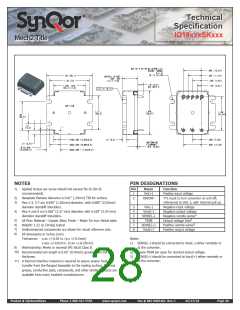
PIN DESIGNATIONS
NOTES
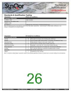
1)
Applied torque per screw should not exceed 5in-lb (3in-lb
recommended).
Pin
Name
Function
Positive input voltage
TTL input to turn converter on and off,
1
Vin(+)
2)
3)
Baseplate flatness tolerance is 0.01” (.25mm) TIR for surface.
Pins 1-3, 5-7 are 0.040” (1.02mm) diameter, with 0.080” (2.03mm)
diameter standoff shoulders.
2
ON/OFF
referenced to Vin(–), with internal pull up.
Negative input voltage
Negative output voltage
Negative remote sense
Output voltage trim
3
4
5
6
7
8
Vin(–)
Vout(–)
SENSE(–)
TRIM
SENSE(+)
Vout(+)
4)
Pins 4 and 8 are 0.062” (1.57 mm) diameter with 0.100" (2.54 mm)
diameter standoff shoulders.
1
2
5)
6)
7)
8)
All Pins: Material – Copper Alloy; Finish – Matte Tin over Nickel plate
Weight: 1.22 oz (34.6g) typical
Undimensioned components are shown for visual reference only.
All dimensions in inches (mm)
3
Positive remote sense
Positive output voltage
Tolerances: x.xx +/-0.02 in. (x.x +/-0.5mm)
x.xxx +/-0.010 in. (x.xx +/-0.25mm)
Workmanship: Meets or exceeds IPC-A610 Class II
Notes:
1)
SENSE(–) should be connected to Vout(–) either remotely or
at the converter.
9)
10) Recommended pin length is 0.03” (0.76mm) greater than the PCB
thickness.
11) A thermal interface material is required to assure proper heat
transfer from the flanged baseplate to the cooling surface. Thermal
grease, conductive pads, compounds, and other similar products are
available from many heatsink manufacturers.
2)
3)
Leave TRIM pin open for nominal output voltage.
SENSE(+) should be connected to Vout(+) either remotely or
at the converter.
Product # IQ18xxxSKxxx
Phone 1-888-567-9596
www.synqor.com
Doc.# 005-0005462 Rev. C
05/27/10
Page 28

 SYNQOR [ SYNQOR WORLDWIDE HEADQUARTERS ]