Technical
Specification
IQ18xxxSKxxx
Application Section
BASIC OPERATION AND FEATURES
CONTROL FEATURES
This converter series uses a two-stage power conversion
topology. The first stage is a buck-converter that keeps the
output voltage constant over variations in line, load, and
temperature. The second stage uses a transformer to provide
the functions of input/output isolation and voltage step-up or
step-down to achieve the output voltage required.
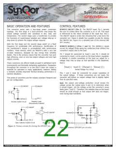
REMOTE ON/OFF (Pin 2): The ON/OFF input, Pin 2, permits
the user to control when the converter is on or off. This input
is referenced to the return terminal of the input bus, Vin(-).
The ON/OFF signal is active low (meaning that a low turns the
converter on). Figure A details four possible circuits for driving
the ON/OFF pin. Figure B is a detailed look of the internal ON/
OFF circuitry.
Both the first stage and the second stage switch at a fixed
frequency for predictable EMI performance. Rectification of
the transformer’s output is accomplished with synchronous
rectifiers. These devices, which are MOSFETs with a very low
on-state resistance, dissipate far less energy than Schottky
diodes. This is the primary reason that the converter has such
high efficiency, even at very low output voltages and very high
output currents.
REMOTE SENSE(+) (Pins 7 and 5): The SENSE(+) inputs
correct for voltage drops along the conductors that connect the
converter’s output pins to the load.
Pin 7 should be connected to Vout(+) and Pin 5 should be
connected to Vout(-) at the point on the board where regulation
is desired. A remote connection at the load can adjust for a
voltage drop only as large as that specified in this datasheet,
that is
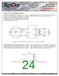
These converters are offered totally encased to withstand harsh
environments and thermally demanding applications. Dissipation
throughout the converter is so low that it does not require a
heatsink for operation in many applications; however, adding
a heatsink provides improved thermal derating performance in
extreme situations.
[Vout(+) - Vout(-)] – [Vsense(+) - Vsense(-)] <
Sense Range % x Vout
Pins 7 and 5 must be connected for proper regulation of
the output voltage. If these connections are not made, the
converter will deliver an output voltage that is slightly higher
than its specified value.
This series of converters use the industry standard footprint and
pin-out configuration.
Note: the output over-voltage protection circuit senses the
voltage across the output (pins 8 and 4) to determine when
it should trigger, not the voltage across the converter’s sense
leads (pins 7 and 5). Therefore, the resistive drop on the board
should be small enough so that output OVP does not trigger,
even during load transients.
ON/OFF
ON/OFF
Vin(_)
Vin(_)
Remote Enable Circuit
Negative Logic
(Permanently Enabled)
5V
5V
ON/OFF
50k
50k
TTL/
CMOS
ON/OFF
Vin(_)
ON/OFF
Vin(_)
50k
50k
TTL
100pF
100pF
Vin(_)
Open Collector Enable Circuit
Direct Logic Drive
Figure A: Various circuits for driving the ON/OFF pin.
Figure B: Internal ON/OFF pin circuitry
Product # IQ18xxxSKxxx
Phone 1-888-567-9596
www.synqor.com
Doc.# 005-0005462 Rev. C
05/27/10
Page 22

 SYNQOR [ SYNQOR WORLDWIDE HEADQUARTERS ]