Technical
Specification
IQ18xxxSKxxx
Application Section
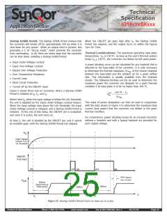
Startup Inhibit Period: The Startup Inhibit Period ensures that When the ON/OFF pin goes high after t2, the Startup Inhibit
the converter will remain off for approximately 200 ms when it is Period has elapsed, and the output turns on within the typical
shut down for any reason. When an output short is present, this Turn-On Time.
generates a 5 Hz “hiccup mode,” which prevents the converter
from overheating. In all, there are seven ways that the converter
can be shut down, initiating a Startup Inhibit Period:
Thermal Considerations: The maximum operating base-plate
temperature, TB, is 100 ºC. As long as the user’s thermal system
keeps TB < 100 ºC, the converter can deliver its full rated power.
•ꢀ InputꢀUnder-VoltageꢀLockout
•ꢀ InputꢀOver-VoltageꢀLockout
•ꢀ OutputꢀOver-VoltageꢀProtection
•ꢀ OverꢀTemperatureꢀShutdown
•ꢀ CurrentꢀLimit
A power derating curve can be calculated for any heatsink that is
attached to the base-plate of the converter. It is only necessary
to determine the thermal resistance, RTHBA, of the chosen heatsink
between the base-plate and the ambient air for a given airflow
rate. This information is usually available from the heatsink
vendor. The following formula can the be used to determine the
maximum power the converter can dissipate for a given thermal
condition if its base-plate is to be no higher than 100 ºC.
•ꢀ ShortꢀCircuitꢀProtection
•ꢀ TurnedꢀoffꢀbyꢀtheꢀON/OFFꢀinput
Figure E shows three turn-on scenarios, where a Startup Inhibit
Period is initiated at t0, t1, and t2:
100 ºC - TA
Pmax
=
diss
RTH
BA
Before time t0, when the input voltage is below the UVL threshold,
the unit is disabled by the Input Under-Voltage Lockout feature.
When the input voltage rises above the UVL threshold, the Input
Under-Voltage Lockout is released, and a Startup Inhibit Period is
initiated. At the end of this delay, the ON/OFF pin is evaluated,
and since it is active, the unit turns on.
This value of power dissipation can then be used in conjunction
with the data shown in Figure 2 to determine the maximum load
current (and power) that the converter can deliver in the given
thermal condition.
For convenience, power derating curves for an encased converter
without a heatsink and with a typical heatsink are provided for
each output voltage.
At time t1, the unit is disabled by the ON/OFF pin, and it cannot
be enabled again until the Startup Inhibit Period has elapsed.
V
in
Under-Voltage
Lockout Turn-
On Threshold
ON/OFF
(neg logic)
ON
OFF
ON
OFF
ON
9ms (typical
turn on time)
V
out
200ms
(typical start-up
inhibit period)
200ms
200ms
t
t0
t1
t2
Figure E: Startup Inhibit Period (turn-on time not to scale)
Product # IQ18xxxSKxxx
Phone 1-888-567-9596
www.synqor.com
Doc.# 005-0005462 Rev. C
05/27/10
Page 25

 SYNQOR [ SYNQOR WORLDWIDE HEADQUARTERS ]