Technical
Specification
IQ18xxxSKxxx
Application Section
APPLICATION CONSIDERATIONS
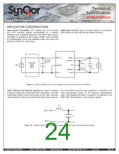
Input System Instability: This condition can occur because Application Circuits: Figure C provides a typical circuit diagram
any dc-dc converter appears incrementally as a negative which details the input filtering and voltage trimming.
resistance load. A detailed application note titled “Input System
Instability” is available on the SynQor website which provides
an understanding of why this instability arises, and shows the
preferred solution for correcting it.
Vout(+)
Vin(+)
Electrolytic
Capacitor
Vsense(+)
External
Input
Filter
Rtrim-up
Vin
Trim
or
ON/OFF
Vin(_)
Cload
Rtrim-down
Iload
Vsense(_)
Vout(_)
Figure C: Typical application circuit (negative logic unit, permanently enabled).
Input Filtering and External Capacitance: Figure D provides The recommended external input capacitance is specified in the
a diagram showing the internal input filter components. This filter Input Characteristics section on the Electrical Characteristics
dramatically reduces input terminal ripple current, which otherwise page. More detailed information is available in the application note
could exceed the rating of an external electrolytic input capacitor. titled “EMI Characteristics” on the SynQor website.
L
Vin(+)
C
Vin(_)
Figure D: Internal Input Filter Diagram (component values listed on the specifications page).
Product # IQ18xxxSKxxx
Phone 1-888-567-9596
www.synqor.com
Doc.# 005-0005462 Rev. C
05/27/10
Page 24

 SYNQOR [ SYNQOR WORLDWIDE HEADQUARTERS ]