SyncMOS Technologies International, Inc.
SM89T16R1
8-Bits Micro-controller
With 64KB Flash ROM & 1KB RAM & Two UART & RTC & ADC & PWM embedded
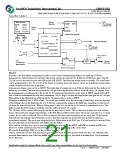
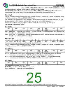
Serial Port Mode 0:
Internal
RxD
Clock Source
PARIN
LOAD
CLOCK
SOUT
Data Bus
P3.0 Alternate
Input function
Mode
1/4
Input
osc/1
osc/16
Write to
SBUF
1/64
1/1024 osc/256
Transmit Shift Register
TX START
TX SHIFT
1/12
SM2
1/4
1
TI
RI
TX CLOCK
Serial Port Interrupt
0
TxD
SHIFT CLOCK
P3.1 Alternate
Input function
RX CLOCK
LOAD SBUF
RX SHIFT
/RI
RX START
REN
READ SBUF
SBUF
CLOCK
RxD
PAROUT
Internal
SBUF
P3.0 Alternate
Input function
Data Bus
SIN
Receive Shift Register
Mode 1
In mode 1, the full duplex asynchronous mode is used. Serial communication frames are made up of 10 bits
transmitted on TxD and received on RxD. The 10 bits consist of a start bit (0), 8 data bits (LSB first), and a stop bit
(1). On receive; the stop bit goes into RB8 in the SFR SCON. The baud rate in this mode is variable. The serial baud
can be programmed to be 1/16 or 1/32 of the Timer 1 overflow. Since the Timer 1 can be set to different reload values,
a wide variation in baud rates is possible.
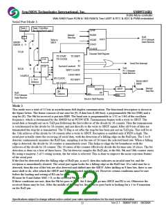
Transmission begins with a write to SBUF. The serial data is brought out on to TxD pin following the first rollover of
divide by 16 counter. The next bit is placed on TxD pin following the next rollover of the divide by 16 counter. Thus
the transmission is synchronized to the divide by 16 counter and not directly to the write to SBUF signal. After all 8
bits of data are transmitted the stop bit is transmitted. The TI flag is set after the stop bit has been put out on TxD pin.
This will be at the 10th rollover of the divide by 16 counter after a write to SBUF.
Reception is enabled only if REN is high. The serial port actually starts the receiving of serial data, with the detection
of the falling edge on the RxD pin; the 1-to-0 detector continuously monitors the RxD line, sampling it at the rate of
16 times the selected baud rate. When a falling edge is detected, the divide by 16 counter is immediately reset. This
helps to align the bit boundaries with the rollovers of the divide by 16 counter.
The 16 states of the counter effectively divide the bit time into 16 slices. The bit detection is done on a best of three
bases. The bit detector samples the RxD pin, at the 8th, 9th and 10th counter states. By using a majority 2 or 3 voting
system, the bit value is selected. This is done to improve the noise rejection feature of the serial port. If the first bit
detected after the falling edge of RxD pin is not 0, then this indicates an invalid start bit, and the reception is
immediately aborted. The serial port again looks for a falling edge in the RxD line. If a valid start bit is detected, then
the rest of the bits are also detected and shifted into the SBUF.
After shifting in 8 data bits, there is one more shift to do, after which the SBUF and RB8 are loaded and RI is set.
However certain conditions must be met before the loading and setting of RI can be done.
RI must be 0 and Either SM2 = 0, or the received stop bit = 1.
If these conditions are met, then the stop bit goes to RB8; the 8 data bits go into SBUF and RI is set. Otherwise the
received frame may be lost. After the middle of the stop bit, the receiver goes back to looking for a 1-to-0 transition
on the RxD pin.
Specifications subject to change without notice contact your sales representatives for the most recent information.
Ver 2.1 SM89T16R1 08/2006
21

 SYNCMOS [ SYNCMOS TECHNOLOGIES,INC ]