SM5953
8-Bit Micro-controller
15KB with ISP Flash
& 256B RAM embedded
9. Interrupt
The SM5953 provides 6 interrupt sources with two priority levels. Each source has its own request flag(s) located in
a special function register. Each interrupt requested by the corresponding flag could individually be enabled or
disabled by the enable bits in SFR’s IE.
When the interrupt occurs, the engine will vector to the predetermined address as given in Table 9-1. Once
interrupt service has begun, it can be interrupted only by a higher priority interrupt. The interrupt service is
terminated by a return from instruction RETI. When an RETI is performed, the processor will return to the
instruction that would have been next when interrupt occurred.
When the interrupt condition occurs, the processor will also indicate this by setting a flag bit. This bit is set
regardless of whether the interrupt is enabled or disabled. Each interrupt flag is sampled once per machine cycle,
and then samples are polled by hardware. If the sample indicates a pending interrupt when the interrupt is enabled,
then interrupt request flag is set. On the next instruction cycle the interrupt will be acknowledged by hardware
forcing an LCALL to appropriate vector address.
Interrupt response will require a varying amount of time depending on the state of microcontroller when the
interrupt occurs. If microcontroller is performing an interrupt service with equal or greater priority, the new interrupt
will not be invoked. In other cases, the response time depends on current instruction.
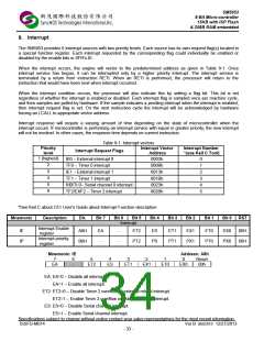
Table 9-1: Interrupt vectors
Priority
level
Interrupt Vector
Address
Interrupt Number
*(use Keil C Tool)
Interrupt Request Flags
1 (highest)
IE0 – External interrupt 0
TF0 – Timer 0 interrupt
0003h
000Bh
0013h
001Bh
0023h
002Bh
0
1
2
3
4
5
2
3
4
5
6
IE1 – External interrupt 1
TF1 – Timer 1 interrupt
RI0/TI 0– Serial channel 0 interrupt
TF2/EXF2 – Timer 2 interrupt
*See Keil C about C51 User’s Guide about Interrupt Function description
Mnemonic
Description
Dir.
Bit 7
Bit 6
Bit 5
Bit 4
Bit 3
Bit 2
Bit 1
Bit 0
RST
Interrupt
Interrupt Enable
register
Interrupt priority
register
IE
IP
A8H
B8H
EA
-
-
-
ET2
PT2
ES
PS
ET1
PT1
EX1
PX1
ET0
PT0
EX0
PX0
00H
00H
Mnemonic: IE
Address: A8h
7
EA
6
-
5
ET2
4
ES
3
ET1
2
EX1
1
ET0
0
EX0
Reset
00h
EA: EA=0 – Disable all interrupt.
EA=1 – Enable all interrupt.
ET2: ET2=0 – Disable Timer 2 overflow or external reload interrupt.
ET2=1 – Enable Timer 2 overflow or external reload interrupt.
ES: ES=0 – Disable Serial channel interrupt.
ES=1 – Enable Serial channel interrupt.
Specifications subject to change without notice contact your sales representatives for the most recent information.
ISSFD-M074 Ver B SM5953 12/27/2013
- 33 -

 SYNCMOS [ SYNCMOS TECHNOLOGIES,INC ]