SM5953
8-Bit Micro-controller
15KB with ISP Flash
& 256B RAM embedded
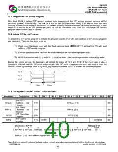
10. Watch Dog Timer
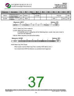
The Watch Dog Timer (WDT) is an 16-bit free-running counter that generate reset signal if the counter overflows.
The WDT is useful for systems which are susceptible to noise, power glitches, or electronics discharge which
causing software dead loop or runaway. The WDT function can help user software recover from abnormal software
condition. The WDT is different from Timer0, Timer1 and Timer2 of general 8052. To prevent a WDT reset can be
done by software periodically clearing the WDT counter. User should check WDR bit of SCONF register whenever
un-predicted reset happened. After an external reset the watchdog timer is disabled and all registers are set to
zeros.
The WDT has selectable divider input for the time base source clock. To select the divider input, the setting of bit2
~ bit0 (PS[2:0]) of Watch Dog Timer Control Register (WDTC) should be set accordingly. As shown in Table 10-1.
To enable the WDT is done by setting 1 to the bit 7 (WDTE) of WDTC. After WDTE set to 1, the 16-bit counter
starts to count with the selected time base source clock which set by PS2~PS0. It will generate a reset signal when
overflows. The WDTE bit will be cleared to 0 automatically when SM5953 been reset, either hardware reset or
WDT reset.
To reset the WDT is done by setting 1 to the bit 5 (CLEAR) of WDTC. This will clear the content of the 16-bit
counter and let the counter re-start to count from the beginning.
Table 10-1: WDT time-out period
Divider
(dividing of Fosc)
PS[2:0]
Time period @ 40MHz
000
001
010
011
100
101
110
111
8
16
32
13.1ms
26.21ms
52.42ms
104.8ms
209.71ms
419.43ms
838.86ms
1677.72ms
64
128
256
512
1024
Clear
WDTF = 0
1. Power on reset
2. External reset
WDR
3. Software write “0”
Fosc
Set WDR = 1
WDTCLK
1
WDT
time-out
select
2PS[2:0]+3
WDT
Counter
WDT time-out
reset
PS[2:0]
Enable/Disable
WDT
Refresh
WDT Counter
WDTEN
WDTC
CLR
Fig. 10-1: Watchdog timer block diagram
Specifications subject to change without notice contact your sales representatives for the most recent information.
ISSFD-M074 Ver B SM5953 12/27/2013
- 35 -

 SYNCMOS [ SYNCMOS TECHNOLOGIES,INC ]