SM5953
8-Bit Micro-controller
15KB with ISP Flash
& 256B RAM embedded
8. Serial interface – UART
The serial buffer consists of two separate registers, a Transmit buffer and a receive buffer.
Writing data to the Special Function Register SBUF sets this data in serial output buffer and starts the transmission.
Reading from the SBUF reads data from the serial receive buffer. The serial port can simultaneously Transmit and
receive data. It can also buffer 1 byte at receive, which prevents the receive data from being lost if the CPU reads
the first byte before transmission of the second byte is completed.
Mnemonic
Description
Dir.
Bit 7
Bit 6
Bit 5
Bit 4
Bit 3
Bit 2
Bit 1
Bit 0
RST
Serial interface 0 and 1
PCON
SCON
Power control
Serial Port control
register
Serial Port data
buffer
87H SMOD
-
-
-
GF1
TB8
GF0
RB8
PD
TI
IDLE
RI
00H
00H
98H
99H
SM0
SM1
SM2
REN
SBUF
SBUF[7:0]
00H
Mnemonic: SCON
Address: 98h
7
SM0
6
SM1
5
SM2
4
REN
3
TB8
2
RB8
1
TI
0
RI
Reset
00H
SM0, SM1: Serial Port 0 mode selection.
SM0
SM1 Mode
0
0
1
1
0
1
0
1
0
1
2
3
The 4 modes in UART, Mode 0 ~ 3, are explained later.
SM2: Enables multiprocessor communication feature
REN: If set, enables serial reception. Cleared by software to disable reception.
TB8: The 9th transmitted data bit in modes 2 and 3. Set or cleared by the CPU depending on
the function it performs such as parity check, multiprocessor communication etc.
RB8: In modes 2 and 3, it is the 9th data bit received. In mode 1, if SM2 is 0, RB8 is the stop
bit. In mode 0, this bit is not used. Must be cleared by software.
TI: Transmit interrupt flag, set by hardware after completion of a serial transfer. Must be
cleared by software.
RI: Receive interrupt flag, set by hardware after completion of a serial reception. Must be
cleared by software.
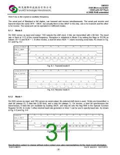
8.1 Serial interface
The Serial Interface can operate in the following 4 modes:
SM0
SM1
Mode
Description
Shift register
8-bit UART
9-bit UART
9-bit UART
Board Rate
0
0
1
1
0
1
0
1
0
1
2
3
Fosc/12
Variable
Fosc/32 or Fosc/64
Variable
Specifications subject to change without notice contact your sales representatives for the most recent information.
ISSFD-M074 Ver B SM5953 12/27/2013
- 29 -

 SYNCMOS [ SYNCMOS TECHNOLOGIES,INC ]