SMS44
DEVI CE OPERATI ON
SUPPLY AN D MONI TOR FUNCTI ONS
7
M S B
0
LS B
6
5
4
3
2
1
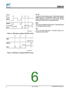
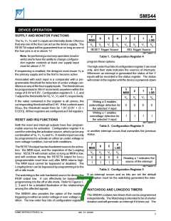
The V0, V1, V2 and V3 inputs are internally diode-ORed so
that any one of the four can act as the device supply. The
RESET# output will be guaranteed true so long as one of
the four pins is at or above 1V.
V3
V2
V1
V0
V3
V2
V1
V0
RESET Trigger Source
IRQ Trigger Source
2047 Table01 1.0
Note:forperformingamemoryoperation(reador
write) and to have the ability to change configura-
tion register contents at least one supply input
must be above 2.7V.
Table 1.
Conf i gurati on Regi ster 4
program these options.
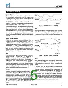
Thehighorderfourbitsofconfigurationregister5areread
only, and their state indicates the sources of interrupts.
Whenever an interrupt is generated the status of the V
inputs will be recorded in the status register. The status
willremainintheregisteruntilthedeviceispowered-down
If sequencing is enabled, the designer must insure V0 is
the primary supply and is the first to become active.
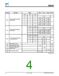
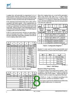
Associated with each input is a comparator with a pro-
grammable threshold for detection of under-voltage con-
ditionsonanyofthefoursupplyinputs. Thethresholdcan
be programmed in 20mV increments anywhere within the
range of 0.9V to 6.0V. Configuration registers 0, 1, 2, and
3 adjust the thresholds for V0, V1, V2 and V3 respectively.
3
M S B
0
2
1
LS B
V3
0
V2
V1
V0
0
If the value contained in the register is all zeroes, the
correspondingthresholdwillbe0.9V. Ifthecontentswere
05HEX the threshold would then be 1.0V [0.9V + (5 ×
0.02V)]. Allfourregistersareconfiguredas8-bitregisters.
Writing a 0 enables
undervoltage detection for
the selected V input
0
1
0
1
Writing a 1 enables
overvoltage detection for
the selected V input
1
1
RESET AN D I RQ FUN CTI ON S
2047 Table02 1.0
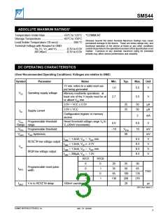
Both the reset and interrupt outputs have four program-
mable sources for activation. Configuration register 4 is
used for selecting the activation source, which can be any
combinationofV0, V1, V2 andV3. Amonitorinputcanonly
be programmed to activate on either an under-voltage or
over-voltage condition, but not both conditions.
Table 2 .
Conf i gurati on Regi ster 5
or another interrupt occurs that overwrites the previous
status.
7
M S B
4
LS B
6
5
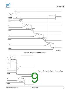
TheRESET#outputhastwohardwiredsourcesforactiva-
tion: the MR# input, and the expiration of the Longdog
timer. RESET# will remain active so long as MR# is low,
and will continue driving the RESET# output for tPRTO
(programmable reset time out) after MR# returns high.
The MR# input cannot be bypassed or disabled. The
Longdog timer can be bypassed by programming it to the
off or idle mode.
V3
0
V2
0
V1
0
V0
0
Reading a 1 indicates the
source of the interrupt
1
1
1
1
2047 Table03 1.0
Table 3.
Conf i gurati on Regi ster 5
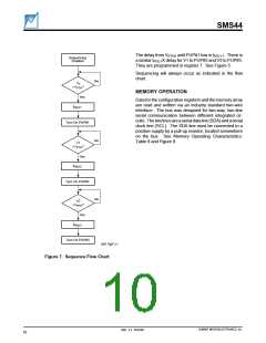
If an interrupt occurs and no bits are set the default
assumption must be the watchdog generated the inter-
rupt.
The watchdog is the sole hardwired source for driving the
IRQ# output low. It can effectively be bypassed by
programming it to the off or idle mode. Refer to Figures 1,
2, 3 and 4 for a detailed illustration of the relationships
among the affected signals.
WATCHDOG AND LONGDOG TI MERS
The SMS44 also provides the option of the monitors
triggering on either an under-voltage or over-voltage con-
dition. The low-order four bits of configuration register 5
The SMS44 contains two timers that can be programmed
independently. TheWatchdogisintendedtobeofshorter
duration and will generate an interrupt if it times out. The
SUMMIT MICROELECTRONICS, Inc.
2047 2.3 10/23/00
7

 SUMMIT [ SUMMIT MICROELECTRONICS, INC. ]