SMM151/152
APPLICATIONS INFORMATION (CONTINUED)
FAULTS
For example, writing 59HEX will allow writes to the
configuration register but not to the memory, while
writing 35HEX will allow writes to the memory but not to
the configuration registers. The SMM151/152 also
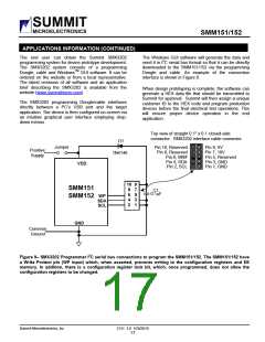
feature a Write Protect pin (WP input) which, when
asserted, prevents writing to the configuration registers
and EE memory. In addition to these two forms of write
protection there is a configuration register lock bit
which, once programmed, does not allow the
configuration registers to be changed.
When either of the COMP1 or COMP2 inputs are in
fault, the open-drain FAULT# output will be pulled low.
A configuration option exists to disable the FAULT#
output while the device is margining. If “Fault Output
Disabled while Margining” is selected, Faults are
disabled for all margining except when margining to the
‘Off’ and ‘Nominal’ states. Also, the programmable
feature ‘Fault Holds Off and Shutdown Control’ is
enabled only for the Nominal margin state.
A2, A1, A0
Please note that if "Fault Output Disabled” is selected
and the device has margined to LOW and HIGH and
then returns to the OFF state without going through
NOMINAL, the Status Register will read a fault (if there
is one) but the FAULT Output Pin will be disabled until
such time that the NOMINAL setting is activated. To
avoid this condition it is recommended that the device
always return to OFF from the NOMINAL state.
The address bits A[2:0] can be hard wired High or Low
or may be left open (High-Z) to allow for a total of 21
distinct device addresses. When floating, the inputs can
tolerate the amount of leakage as described by the
specification IAIT. An external 100k pull-up or pull down
resistor is sufficient to set a High or Low logic level.
CS+, CS-
Select a resistor value that will drop no more than
100mV (full scale) when full load is drawn by the
converter or circuit being sensed by the resistor RS
(Figure 1). To obtain highest accuracy current-sensing,
provide a Kelvin connection from the resistor to the
CS+ and CS- pins. Do not allow the main current path
circuit traces to inadvertently become a part of the
current sense resistor. Kelvin connect directly at the
resistor and follow the manufacturer’s instructions for
exact positioning of the traces for Kelvin sensing.
Fault Latched by a Fault Condition:
The “Fault Latched by a Fault Condition” programmable
option is triggered only on the leading edge of a Fault.
That is, a latched fault can be cleared while the Fault
yet exists.
Fault Latched by Ready I/O Pin:
Fault Latched by Ready I/O pin functions on the margin
transitions from Off to Hi/Low/Nominal or from Nominal
to Hi/Low or Hi/Low to Nominal but not from
Hi/Low/Nominal to Off.
WRITE PROTECTION
Write protection for the SMM151/152 is located in a
volatile register where the power-on state is defaulted
to write protect. There are separate write protect modes
for the configuration registers and memory. In order to
remove write protection, the code 55HEX is written to the
write protection register.Other codes will enable write
protection.
Summit Microelectronics, Inc
2131 3.0 1/20/2010
13

 SUMMIT [ SUMMIT MICROELECTRONICS, INC. ]