USBLC6-2
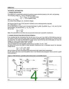
3. HOW TO ENSURE A GOOD ESD PROTECTION
While the USBLC6-2 provides a high immunity to ESD surge, an efficient protection depends on the layout
of the board. In the same way, with the rail to rail topology, the track from the VBUS pin to the power supply
+VCC and from the GND pin to GND must be as short as possible to avoid overvoltages due to parasitic
phenomena (see figure 6).
It’s often harder to connect the power supply near to the USBLC6-2 unlike the ground thanks to the ground
plane that allows a short connection.
To ensure the same efficiency for positive surges when the connections can’t be short enough, we
recommend to put close to the USBLC6-2, between VBUS and ground, a capacitance of 100nF to prevent
from these kinds of overvoltage disturbances (see figure 7).
The add of this capacitance will allow a better protection by providing during surge a constant voltage.
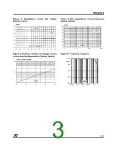
The figures 8, 9 and 10 show the improvement of the ESD protection according to the recommendations
described above.
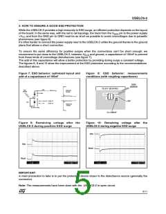
Figure 7: ESD behavior: optimized layout and
add of a capacitance of 100nF
Figure 8: ESD behavior: measurements
conditions (with coupling capacitance)
ESD
SURGE
V
CL
+
TEST BOARD
Lw
ESD
SURGE
POSITIVE
SURGE
REF2=+V
CC
C=100nF
t
t
I/O
V
V
+ = V +V surge >0
CC
CL
F
+5V
VI/O
surge <0
- = -V
CL
F
NEGATIVE
SURGE
REF1=GND
V -
CL
C=100nF
Figure 9: Remaining voltage after the
USBLC6-2 during positive ESD surge
Figure 10: Remaining voltage after the
USBLC6-2 during negative ESD surge
Vin
Vin
Vout
Vout
IMPORTANT:
A main precaution to take is to put the protection device closer to the disturbance source (generally the
connector).
Note: The measurements have been done with the USBLC6-2 in open circuit.
5/11

 STMICROELECTRONICS [ ST ]